Emergency lighting

a technology for emergency lighting and lighting, applied in the field of emergency lighting, can solve the problems of obstructing and restricting the access to the aisle of other passengers, inoperable electrical lighting system, and broken electrical connections, and achieves the effect of reducing or preventing the generation, low profile, and easy repair

Inactive Publication Date: 2005-04-05
SAF T GLOW LTD
View PDF6 Cites 20 Cited by
  • Summary
  • Abstract
  • Description
  • Claims
  • Application Information

AI Technical Summary

Benefits of technology

More particularly, the present invention concerns a photoluminescent track that is of simple construction that facilitates manufacture and assembly.
The position of the floor mounted track is fixed on installation of the emergency lighting system and, to accommodate changes in the seating layout, it is preferred to provide the seat units with a photoluminescent track on the side of the aisle seat, preferably close to the floor. The track on the aisle seats is provided in addition to the existing floor track and will provide an escape route for passengers to follow where the floor track is concealed by the seat unit. In this way, the appearance of a substantially continuous track along each side of the aisle leading to an exit may be maintained without modification to the floor track.

Problems solved by technology

Furthermore, as passengers move along the aisle, they obstruct and restrict access to the aisle of other passengers in the rows.
However, in an emergency following an accident, the electrical lighting system may be inoperable if the electrical connections to the power source are damaged.
For example, the electrical connections may be broken by impact damage to the structure of the vehicle or by outbreak of a fire following a crash.
Moreover, even if the lighting system remains operable, the outbreak of fire may render the lighting system ineffective if the light is blocked by smoke filling the interior of the vehicle.
The lighting system may also fail in other circumstances without an accident due to faults arising in normal service making it difficult for passengers to leave the vehicle safely at night or in conditions of low ambient light.
The provision of a separate emergency lighting system adds considerably to the costs for initial installation and subsequent maintenance in service with regular checks to ensure operability.
The resulting delay is inconvenient for passengers and adds to the running cost for the aircraft operator, especially if a take-off slot has to be vacated.
A further problem of such electrical emergency lighting systems is the extra weight of the storage batteries normally employed as the separate power source which adds to operating costs.
Thus, fuel costs may be increased and / or, in the case of aircraft, the number of passengers may have to be reduced to compensate for the extra weight.
The most important disadvantage of the known electrical emergency lighting systems however, is probably that they suffer from the same problem of the electrical connections being broken in a crash resulting from structural damage to the vehicle and / or from fire.
Accordingly, such emergency lighting systems can be rendered inoperative just at the very time they are required to assist passengers to evacuate the vehicle.

Method used


Image

  • Emergency lighting
  • Emergency lighting
  • Emergency lighting

Examples


Embodiment Construction

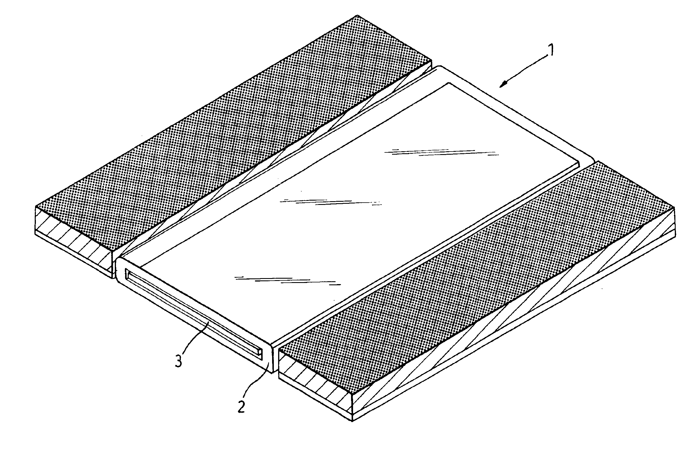
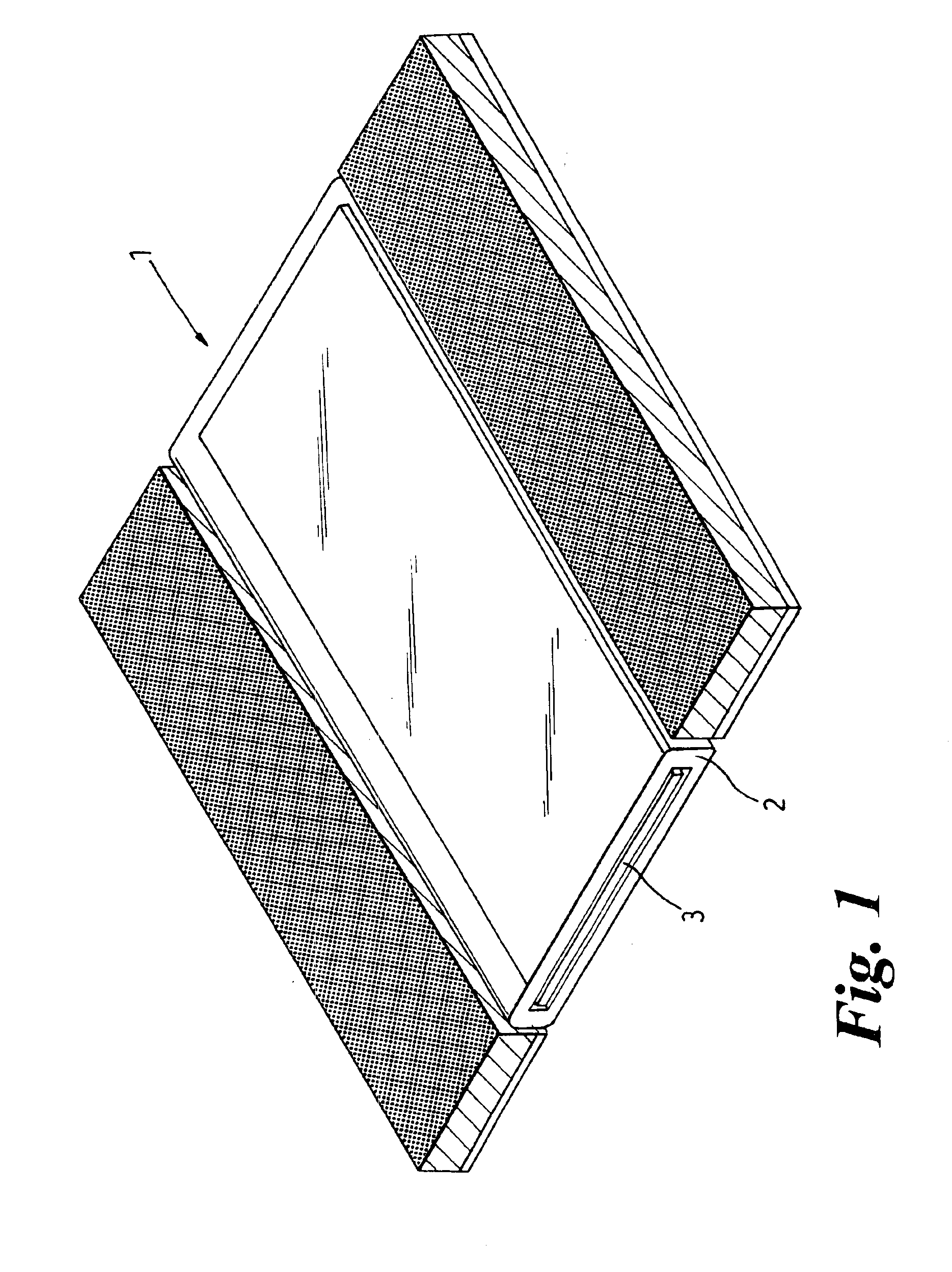
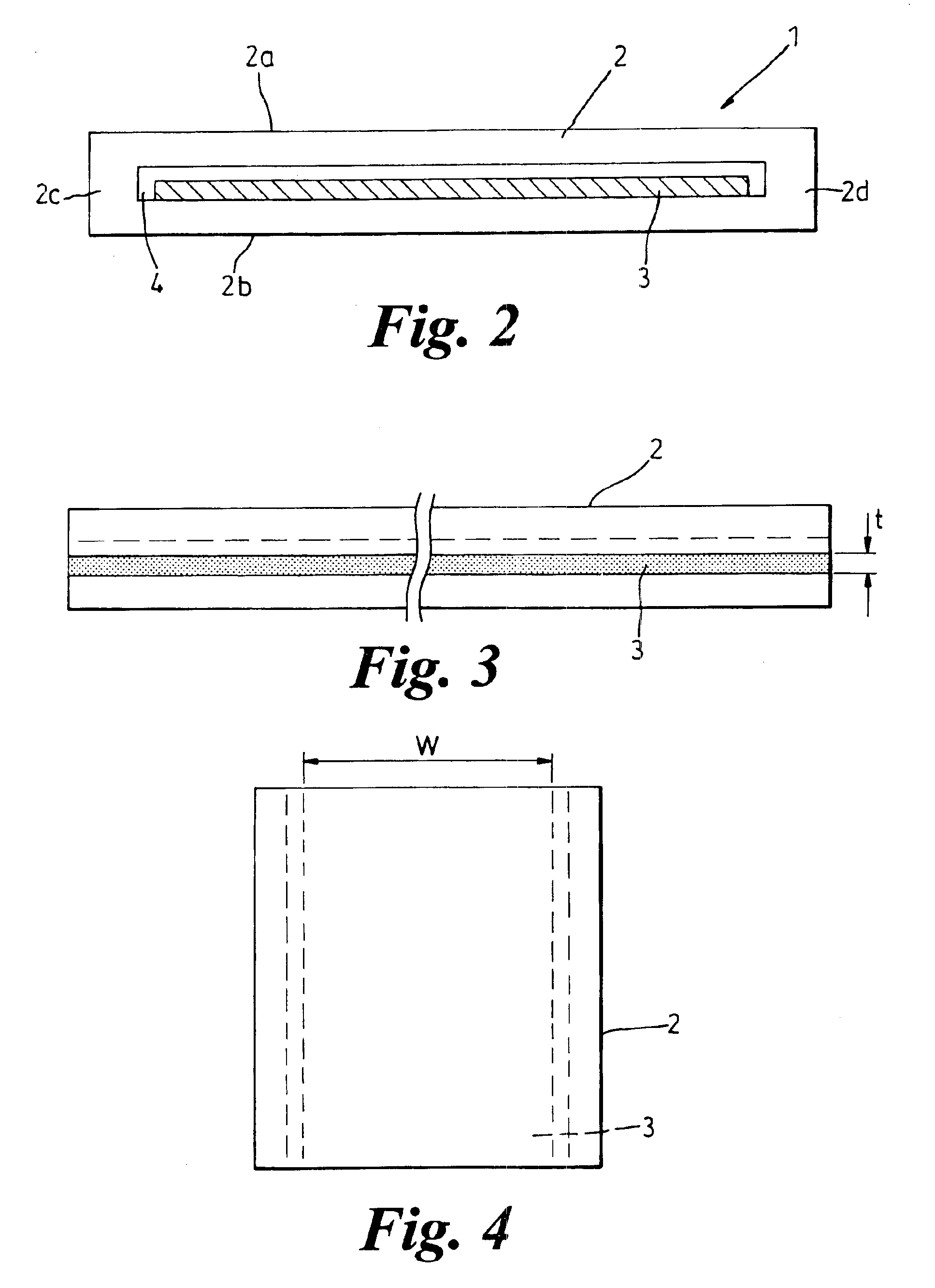
Referring first to FIGS. 1 to 5 of the drawings, a photoluminescent track 1 is shown comprising an elongate hollow housing 2 of uniform, generally rectangular cross-section and an elongate insert 3. The housing 2 has flat upper and lower walls 2a and 2b respectively connected by opposed side walls 2c, 2d to define therebetween a substantially rectangular slot 4.

The insert 3 has a width ‘w’ and thickness ‘t’ slightly less than the corresponding dimensions of the slot 4 to provide limited clearance for push-fitting the insert 3 in the slot 4 from one end of the housing 2. The insert 3 extends the length of the slot 4 between the ends of the housing 2 and the width of the slot 4 between the sides of the housing 2.

The dimensions of the housing 2 and insert 3 are chosen so that the insert 3 emits light over a major part, preferably at least 75% and more preferably at least 90%, of the surface of the upper wall 2a of the housing 2 overlying the photoluminescent material.

As best shown in F...


PUM


Abstract

An emergency lighting system for an aircraft has photoluminescent material arranged to define an escape path to the exits. The photoluminescent material is encapsulated within a track of predetermined length for securing to the floor of the aircraft. The track comprises a one piece housing formed with a longitudinally extending slot and the photoluminescent material is provided by an insert that is a push-fit in the slot from one end of the housing. The housing is closed at both ends to seal the slot and prevent ingress of dirt or fluid. In a modification the housing is compressed with the insert in place to reduce the height of the track and optionally to provide the track with anti-slip characteristics.

Description

BACKGROUND OF THE INVENTIONThis invention concerns improvements in or relating to emergency lighting, especially emergency lighting used to indicate an escape path leading to an exit for evacuation of a passenger vehicle in an emergency, for example following an accident.The invention has particular application to passenger vehicles of the type in which rows of seats are provided on either side of an aisle with an exit at one or both ends of the aisle and / or on one or both sides of the aisle between the ends. Examples of this type of passenger vehicle include aircraft, trains and coaches.Vehicles of this type are designed to carry a large number of passengers in a confined space. For example, each row may seat two or three passengers on each side of the aisle which is normally only wide enough for one passenger to move along between the aisle seats.As a result, there may be several passengers in each row who have to access the aisle one at a time and move along the aisle to an exit....

Claims


Application Information

Patent Timeline
Patent Type & Authority Patents(United States)
IPC IPC(8): B64D25/00F21K2/00G09F13/20G09F19/22A62B3/00
CPCA62B3/00B64D25/00F21K2/00G09F19/228G09F13/20G09F19/22G08B7/066
Inventor STOKES, PETER DAVIDBODLE, PETER WINSTANLEY
Owner SAF T GLOW LTD
Why Eureka
Try Eureka