Antifriction bearing and process for producing outer race for use in antifriction bearing

Inactive Publication Date: 2005-04-05
KOYO SEIKO CO LTD
View PDF9 Cites 11 Cited by
  • Summary
  • Abstract
  • Description
  • Claims
  • Application Information

AI Technical Summary

Benefits of technology

The process of the invention is adapted to produce an antifriction bearing outer race wherein a portion thereof from an outer peripheral surface thereof to a depth of 3 mm has a hardness of 58 to 62 in HRC and a hardness gradient of up to 1 HRC/1 mm from the outer peripheral surface inward, the depth portion containing 5 to 18 vol. % of retained austenite, a portion of the outer race from an inner peripheral surface thereof to a depth of 1 mm having a hardness of 61 to 64 in HRC and containing 5 to 15 vol. % of retained austenite. The outer race blank is heated at 800 to 880° C. for 1 to 3 hours and thereafter treated merely by hardening the blank in the quenching oil, injecting the quenching oil into the oil against the inner peripheral surface of the blank at a pressure of 0.2 to 0.8 kg/cm2 and similarly injecting the quenching oil against the outer peripheral surface of the blank at a pressure of 1.4 to 2.1 kg/cm2. Accordingly, the outer race can be produced at a lower cost than the conventional process including a carburizing or carbonitriding treatment.
In

Problems solved by technology

An elongated rolling fatigue life is of course required of these antifriction bearings for use under the lubricating conditions involving the use of a lubricant containing extraneous matter, while also required are the resistance of the outer race to breaking and the resistance of the outer race to plastic deformation due to the heat of or load on the outer race, because if the outer race breaks, the rolling line must be brought out of operation, and because the plastic deformation of the outer race impairs the q

Method used


Image

  • Antifriction bearing and process for producing outer race for use in antifriction bearing
  • Antifriction bearing and process for producing outer race for use in antifriction bearing
  • Antifriction bearing and process for producing outer race for use in antifriction bearing

Examples


first embodiment

antifriction bearing of the invention will be described below.

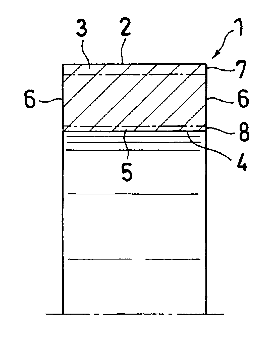
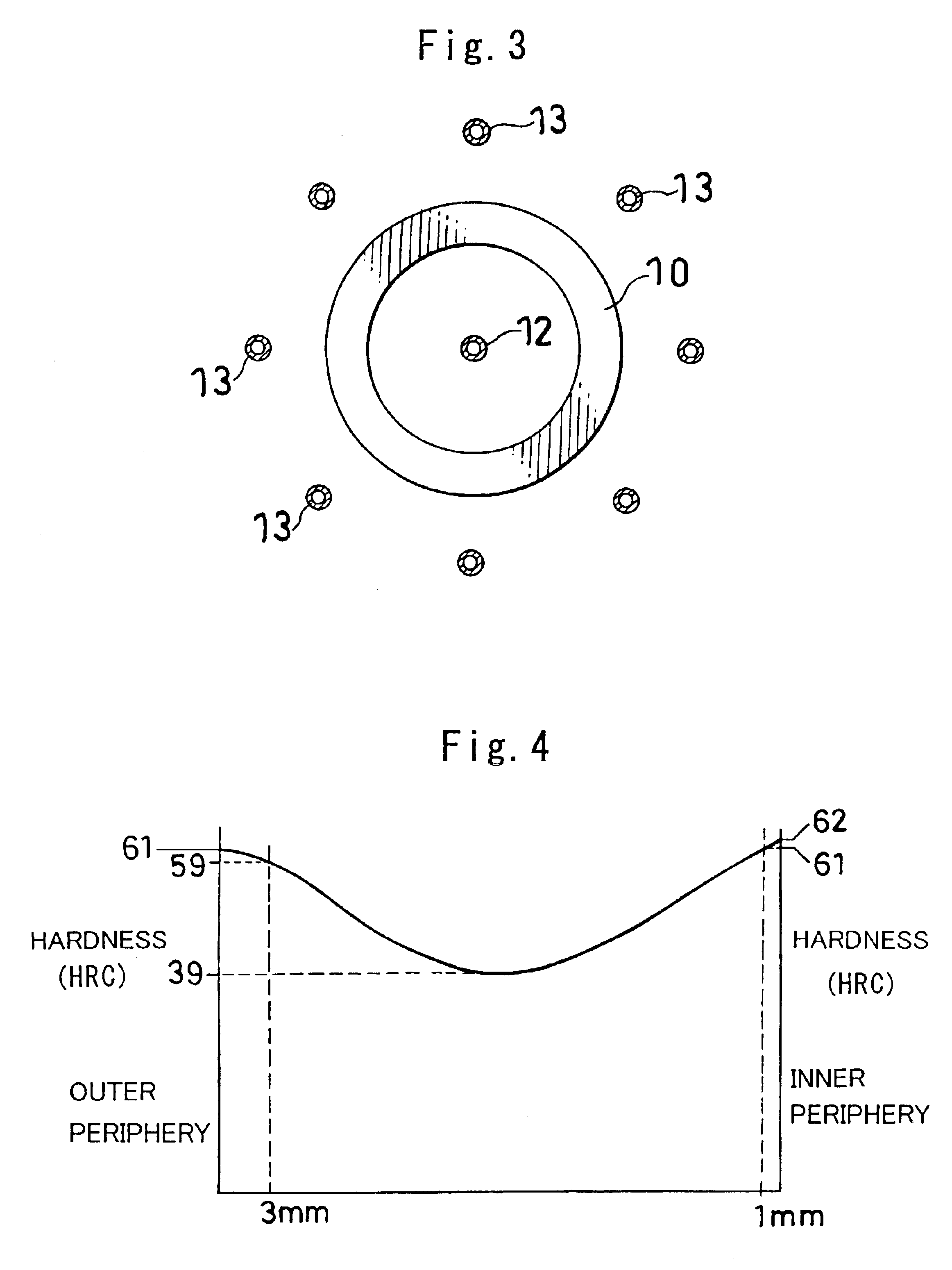
With reference to FIG. 1 showing the outer race of an antifriction bearing for use as a backup roll in a multistage rolling machine, a portion 3 of the outer race 1 from the outer peripheral surface 2 thereof to a depth of 3 mm has a hardness of 58 to 62 in HRC and a hardness gradient of up to 1 HRC / 1 mm from the outer peripheral surface 2 inward. A portion 5 of the outer race 1 from the inner peripheral surface 4 thereof to a depth of 1 mm has a hardness of 61 to 64 in HRC. The center portion of the thickness of the outer race 1 between the inner and outer peripheral surfaces 4, 2 thereof has a hardness of 35 to 42 in HRC. The outer race 1 has such a distribution of hardnesses in the direction of its thickness that the hardness in terms of HRC of the race gradually decreases from the inner and outer peripheral surfaces 4, 2 toward the center portion of the thickness and varies smoothly. The portion 3 of the outer race 1 ...


PUM

PropertyMeasurementUnit
Lengthaaaaaaaaaa
Lengthaaaaaaaaaa
Lengthaaaaaaaaaa

Abstract

An antifriction bearing comprises an inner race, an outer race having an outer peripheral surface to be brought into contact with other member for use as a roll, and a plurality of rolling elements arranged between the inner and outer races. The portion of the outer race from an outer peripheral surface thereof to a depth of 3 mm has a hardness of 58 to 62 in Rockwell C hardness (hereinafter referred to as “HRC”) and a hardness gradient of up to 1 HRC/1 mm from the outer peripheral surface inward, and contains 5 to 18 vol. % of retained austenite. The portion of the outer race from an inner peripheral surface thereof to a depth of 1 mm has a hardness of 61 to 64 in HRC and contains 5 to 15 vol. % of retained austenite. The center portion of the thickness of the outer race between the inner and outer peripheral surfaces thereof has a hardness of 35 to 42 in HRC. The outer race can be prevented from cracking or breaking and from undergoing plastic deformation due to use for a short period of time.

Description

BACKGROUND OF THE INVENTIONThe present invention relates to antifriction bearings comprising an inner race, an outer race having an outer peripheral surface to be brought into contact with other member for use as a roll, and rolling elements arranged between the inner and outer races, and to a process for producing an outer race for use in antifriction bearings.The outer races of antifriction bearings are used, for example, as backup rolls in multistage rolling machines. Such antifriction bearings are generally used with a lubricant containing extraneous matter becoming mixed therewith. An elongated rolling fatigue life is of course required of these antifriction bearings for use under the lubricating conditions involving the use of a lubricant containing extraneous matter, while also required are the resistance of the outer race to breaking and the resistance of the outer race to plastic deformation due to the heat of or load on the outer race, because if the outer race breaks, the...

Claims


Application Information

Patent Timeline
IPC IPC(8): C21D9/40F16C33/58F16C33/62C22C38/00C22C38/18C22C38/44F16C13/00F16C33/64
CPCC21D9/40F16C33/62F16C33/58
Inventor GOTO, MASAOKIZAWA, KATSUHIKO
Owner KOYO SEIKO CO LTD
Why Eureka
Try Eureka