Chemical mechanical polishing pad having holes and or grooves

a technology of mechanical polishing pad and hole, which is applied in the direction of flexible wheel, manufacturing tool, lapping machine, etc., can solve the problems of uneven polishing of wafers, uneven distribution of slurry in the radial direction and considerable difference in the polishing rate of the polishing pad between the central portion and the peripheral portion

Inactive Publication Date: 2005-04-05
RION SMI
View PDF7 Cites 25 Cited by
  • Summary
  • Abstract
  • Description
  • Claims
  • Application Information

AI Technical Summary

Benefits of technology

[0015]Therefore, an object of the invention is to provide a CMP pad for a CMP process which is formed with holes, grooves or a combination thereof capable of retarding the discharge rate of a slurry supplied onto a polishing surface while uniformly distributing the slurry over the polishing surface.

Problems solved by technology

Thus, the slurry is non-uniformly distributed in the radial direction of the polishing pad.
Due to such a non-uniform distribution of the slurry, the wafer is non-uniformly polished because its polishing rate is varied depending on a radial position of the polishing pad in contact with the wafer's surface.
As a result, the polishing pad exhibits a considerable difference in polishing rate between its central portion and its peripheral portion.
Due to this pressure, however, it may be difficult for the slurry to reach the central portion of the wafer.
As a result, the wafer is non-uniformly polished.
However, such a polishing pad having circular or spiral grooves cannot meet various conditions required in a CMP process because it has a fixed pattern formed only of grooves.
As a result, a degradation in polishing rate occurs at the central portion of the wafer.
However, this polishing pad has a drawback in that each groove has an insufficient depth corresponding to ¼ of the thickness of the polishing pad.
Since the grooves or holes formed on the above mentioned conventional polishing pads have a fixed pattern such as concentric circles or a lattice, it is difficult to form a groove pattern capable of effectively controlling the flow of a slurry.
Since the holes have a simple and fixed pattern, it is difficult to arrange them to have diverse hole patterns desired in a CMP process.

Method used


Image

  • Chemical mechanical polishing pad having holes and or grooves
  • Chemical mechanical polishing pad having holes and or grooves
  • Chemical mechanical polishing pad having holes and or grooves

Examples


Embodiment Construction

ss="d_n">[0026]FIG. 7 is a schematic view illustrating a polishing pad having a plurality of concentric circles of different diameters each composed of a plurality of holes;

[0027]FIG. 8 is a schematic view illustrating a polishing pad which is divided into two radial regions each having a plurality of concentric circles of different diameters each composed of a plurality of holes; and

[0028]FIGS. 9 and 10 are schematic views respectively illustrating CMP pads each having a plurality of concentric circles of different diameters each composed of grooves, holes, or a combination thereof.

BEST MODE FOR CARRYING OUT THE INVENTION

[0029]Now, the present invention will be described in detail in terms of its constitution and function, with reference to the annexed drawings.

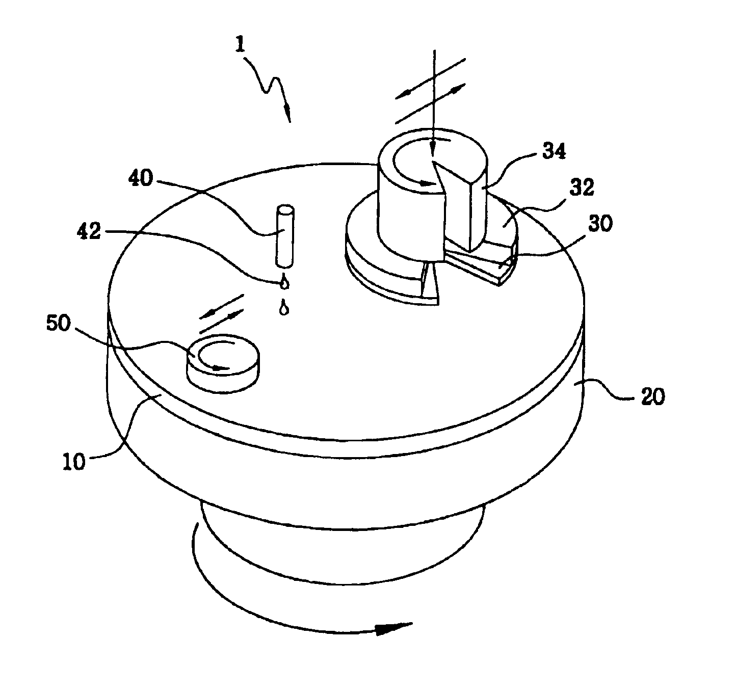
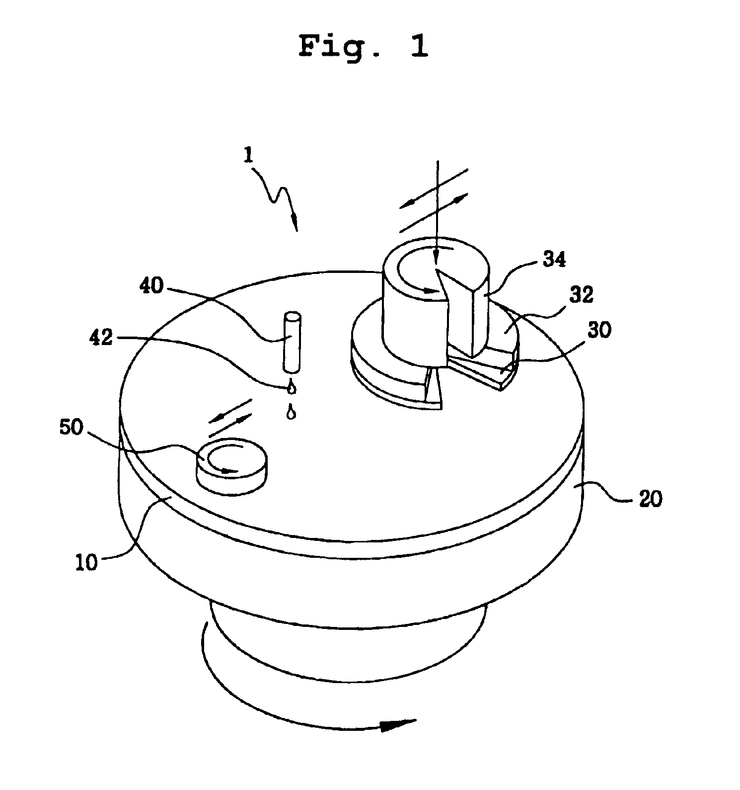
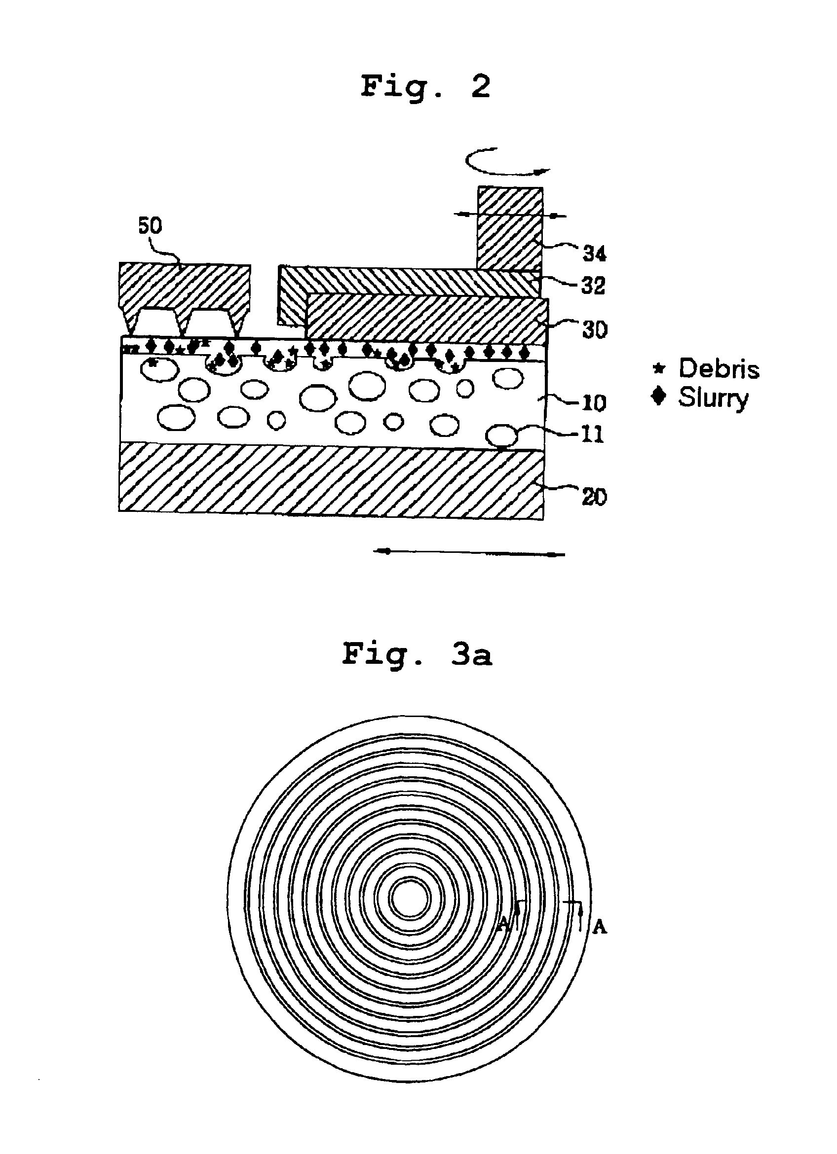
[0030]In accordance with the present invention, a CMP pad is provided which has, at a polishing surface thereof, a plurality of concentric circles each having grooves, holes, or a combination thereof. Referring to FIG. 5, di...


PUM


Abstract

Disclosed is a chemical mechanical polishing pad formed with holes, grooves or a combination thereof. The chemical mechanical polishing pad is characterized in that a plurality of concentric circles each having grooves, holes, or a combination thereof are formed at a polishing surface of the polishing pad. The chemical mechanical polishing pad provides effects of effectively controlling a flow of slurry during a polishing process, thereby achieving a stability in the polishing process in terms of a polishing rate, and achieving an enhancement in the planarization of a wafer.

Description

TECHNICAL FIELD[0002]The present invention relates to a polishing pad used in a chemical mechanical polishing process, and more particularly to a chemical mechanical polishing pad formed at a polishing surface thereof with a plurality of concentric circles each having grooves, holes, or a combination thereof.BACKGROUND ART[0003]Generally, chemical mechanical polishing (CMP) is a high precision / mirrored surface polishing method used to obtain global planarization in a semiconductor device manufacturing process. In accordance with such CMP, a slurry is supplied between a polishing pad and a wafer to be polished, so as to chemically etch the surface of the wafer. Using the polishing pad, the etched surface of the wafer is mechanically polished.[0004]Referring to FIG. 1, a typical CMP machine, which is denoted by the reference numeral 1, is schematically illustrated. Also, a CMP method using the CMP machine 1 is schematically illustrated in FIG. 2. The CMP method includes a chemical etc...

Claims


Application Information

Patent Timeline
Patent Type & Authority Patents(United States)
IPC IPC(8): B24B37/04B24D13/00B24D13/14H01L21/02H01L21/304B24B37/00B24B37/26H01L21/306
CPCB24B37/26H01L21/30625H01L21/304
Inventor PARK, INHAKWON, TAE-KYOUNGKIM, JAESEOK
Owner RION SMI
Why Eureka
Try Eureka