Method and apparatus for individually cooling components of electronic systems

Inactive Publication Date: 2005-04-05
VALTRUS INNOVATIONS LTD +1
View PDF33 Cites 94 Cited by
  • Summary
  • Abstract
  • Description
  • Claims
  • Application Information

AI Technical Summary

Benefits of technology

In comparison to known cooling mechanisms and techniques, certain embodiments of the invention are capable of achieving certain aspects, including some or all of the following: (1) substantially focalized supply of cooling fluid to individual heat generating components; (2) independent control of the fluid supply to the heat generating components; (3) energy efficient utilization of a plurality of blowers by ope

Problems solved by technology

Some of the components (e.g., processors, micro-controllers, high speed video cards, disk drives, semi-conductor devices, and the like) of an electronic system (e.g., computer system, entertainment system, and the like) are known to generate relatively significant amounts of heat.
Moreover, it is generally known that the performance and / or reliability of the components typically deteriorate as the temperature of the components increase.
Dissipating the heat generated by these components becomes ever more difficult as the electronic systems incorporate greater numbers of components.
Conventional cooling systems may be unable to adequately cool these types of electronic systems.
For instance, the cooling fluid flow across a PC board may be relatively impeded by installation of the additional components blocking the fluid flow.
In addition, the tangential, unidirectional nature of the fluid flow as the number of components increases as well as the number of the subsystems, typically causes the multiple components to be cooled in series.
The resulting size and complexity of these types of cooling systems have substantially detracted from their commercial viability, e.g., by adding additional costs to the overall electronic systems.
In addition, the use of additional blowers generally increases the amount of energy and / or the space required to operate the cooling systems, thereby increasing the operating costs.
In addition, various components in electronic systems typically generate various amounts of heat and thus require various levels of cooling.
In one respect, conventional cooling systems often attempt to cool components that may not be operating at a level which may cause its temperature to exceed the predetermined temperature range.
Consequently, conventional cooling systems often incur a greater amount of operating expense than is necessary to sufficiently cool the heat generating components.

Method used


Image

  • Method and apparatus for individually cooling components of electronic systems
  • Method and apparatus for individually cooling components of electronic systems
  • Method and apparatus for individually cooling components of electronic systems

Examples


first embodiment

The valve controller 304 is configured to receive the measured temperatures of a plurality of heat generating components, e.g., heat generating components 22, 48. In this regard, the controller 304 may comprise a microprocessor, a micro-controller, an application specific integrated circuit, ASIC and the like. The temperatures of the heat generating components may be measured by temperature sensors 306 and 308. Although FIG. 3 illustrates two temperature sensors 306 and 308, it should be understood that the number of temperature sensors is not critical to the operation of the invention. Instead, the cooling system 302 may include any reasonably suitable number of temperature sensors to thus measure the temperatures of any reasonably suitable number of heat generating components. According to a preferred embodiment, the number of temperature sensors and thus the temperature measurements of the number of heat generating components may be upgradable, e.g., scalable, to include any addi...

second embodiment

FIG. 4 shows a block diagram 400 of a second exemplary control scheme for a cooling system 402 according to the present invention. The elements illustrated in the block diagram 400 operate in substantially the same manner as those elements illustrated in the block diagram 300, except that the blower controller 414 is configured to operate independently of the valve controller 404. For example, the valve controller 404 operates in substantially the same manner as the valve controller 302. In this respect, only those elements in the block diagram 400 that differ from those elements in the block diagram 300 will be described hereinbelow. In this respect, interface electronics 420 may be configured to provide an interface between the valve controller 404 and the components for operating the control valves 410 and 412, e.g., a motor to control the opening in the valves, device for operating the pulsating valve (not shown), etc. In addition, interface electronics 422 may be configured to ...


PUM


Abstract

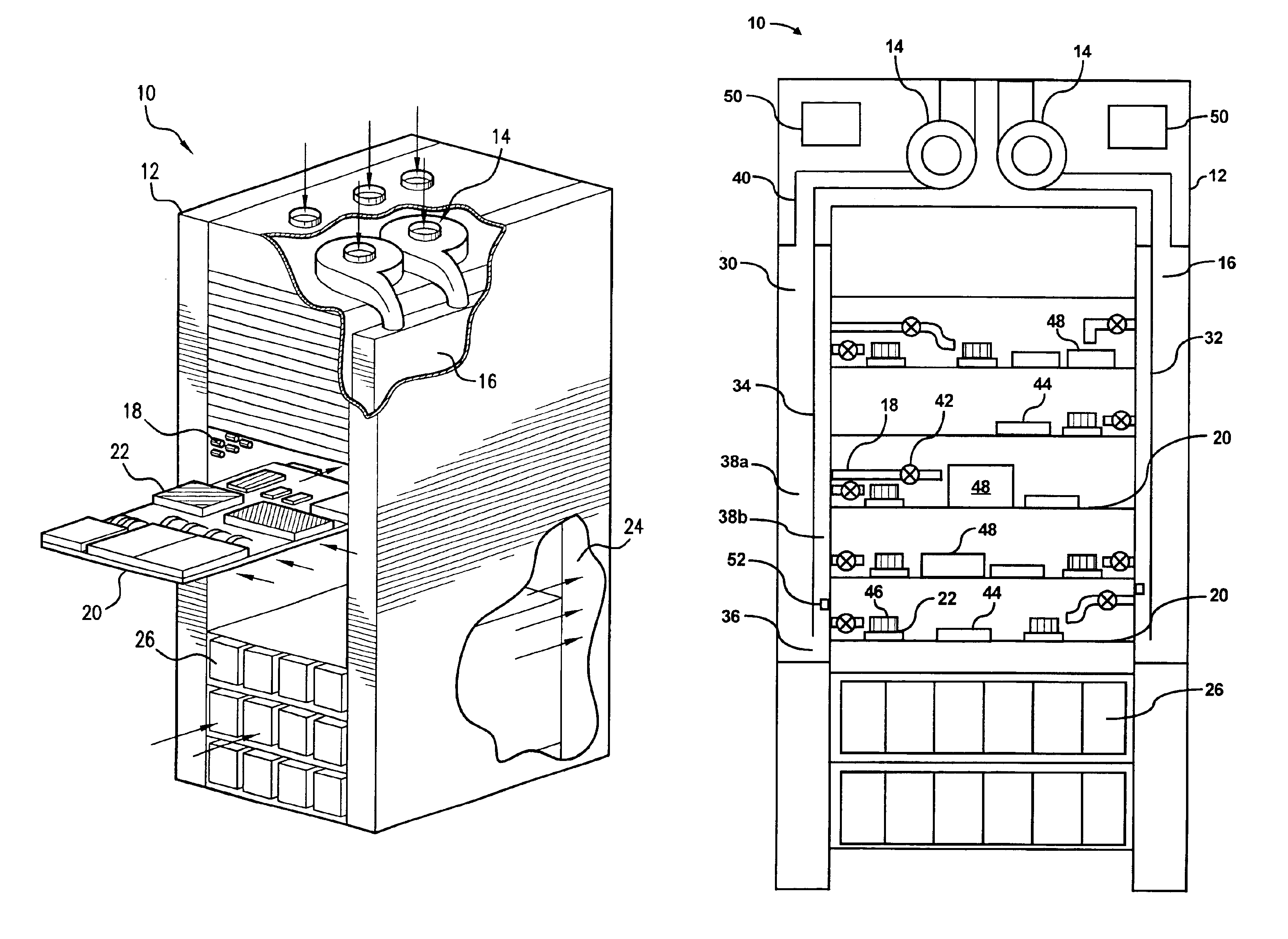
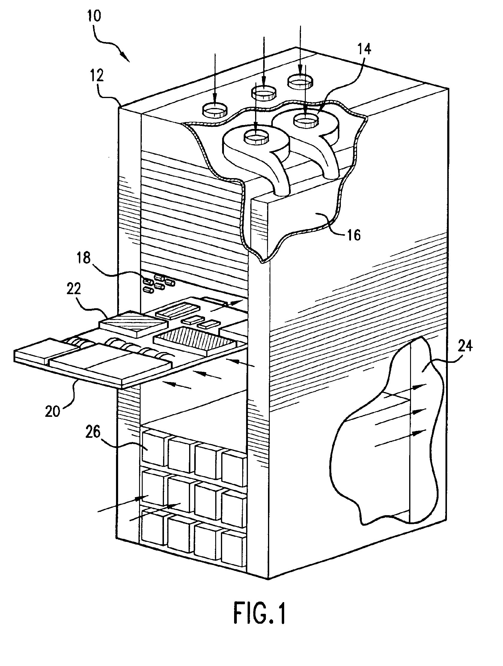
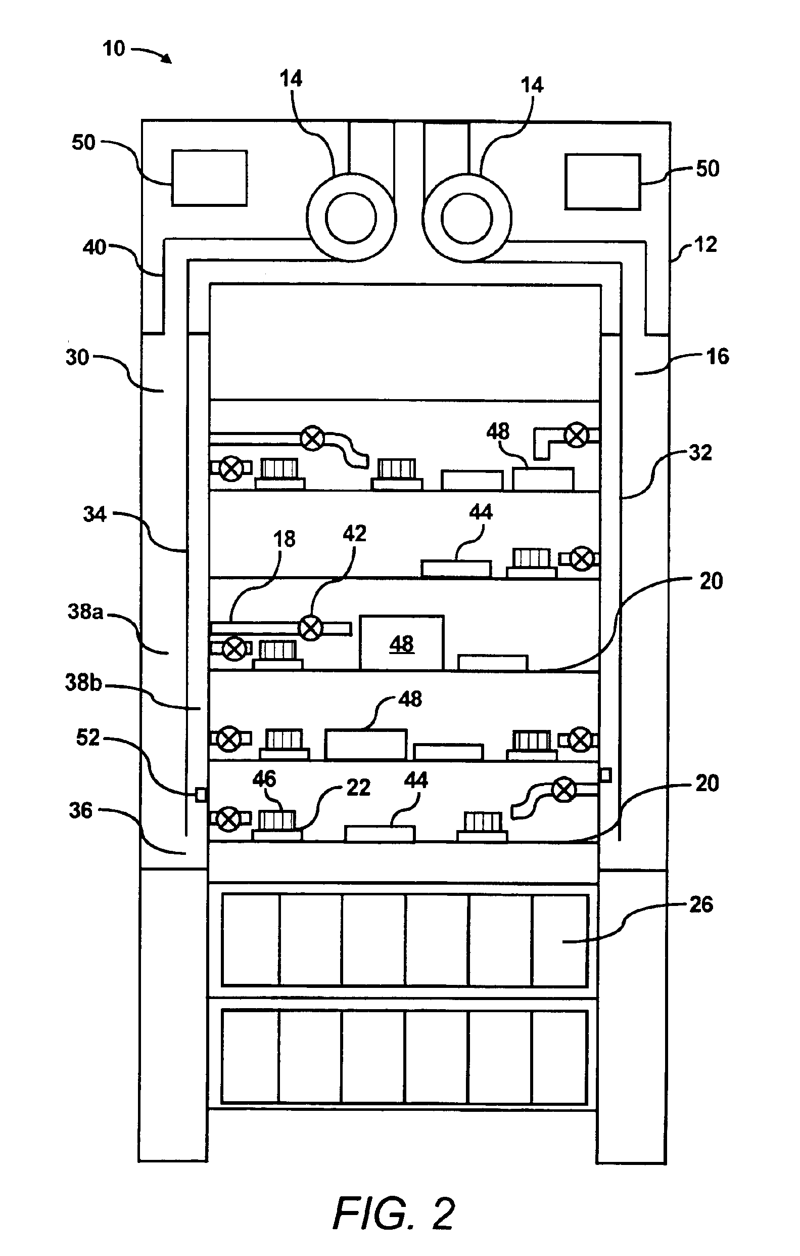
A cooling system is configured to supply individually metered amounts of cooling fluid to heat generating components, e.g., processors, micro-controllers, high speed video cards, disk drives, semi-conductor devices, and the like, of an electronic system. The cooling system includes at least one variable speed fan, e.g., blower, configured to supply fluid through a centralized plenum and thereafter through a plurality of nozzles to the components of the electronic system. Each of the nozzles contains a valve to control the amount of fluid flow through the each of the nozzles. A controller is provided to control the operation of the variable speed fan and the operation of each of the valves is also controlled by a controller. By substantially controlling the amount of cooling fluid supplied to each of the components based upon the amount of heat generated by each component, the cooling system of the present invention may operate in a more efficient manner, thereby requiring substantially less energy than conventional cooling systems.

Description

FIELD OF THE INVENTIONThis invention relates generally to electronic component cooling systems. More particularly, the invention pertains to a cooling system for delivering jets of fluid in individually metered amounts to components of a multi-component system.BACKGROUND OF THE INVENTIONSome of the components (e.g., processors, micro-controllers, high speed video cards, disk drives, semi-conductor devices, and the like) of an electronic system (e.g., computer system, entertainment system, and the like) are known to generate relatively significant amounts of heat. The heat generating components, along with other components of the electronic system, are typically mounted on one or more printed circuit (PC) boards to thereby form a computer subsystem. Moreover, it is generally known that the performance and / or reliability of the components typically deteriorate as the temperature of the components increase. In an effort to improve the performance and / or reliability of electronic system...

Claims


Application Information

Patent Timeline
IPC IPC(8): G06F1/20H05K7/20
CPCG06F1/206H05K7/20727H05K7/20836H05K7/20736Y02B60/1275Y02D10/00
Inventor BEITELMAL, ABDLMONEM H.PATEL, CHANDRAKANT D.
Owner VALTRUS INNOVATIONS LTD
Why Eureka
Try Eureka