System and method for measuring brake mean effective pressure in a running vehicle
- Summary
- Abstract
- Description
- Claims
- Application Information
AI Technical Summary
Benefits of technology
Problems solved by technology
Method used
Image
Examples
Embodiment Construction
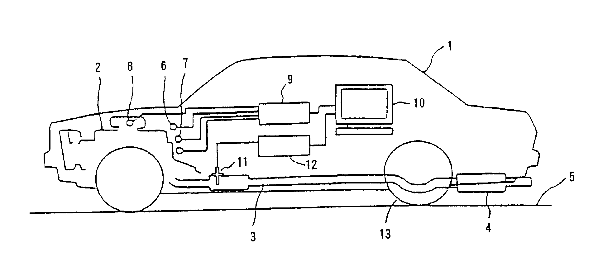
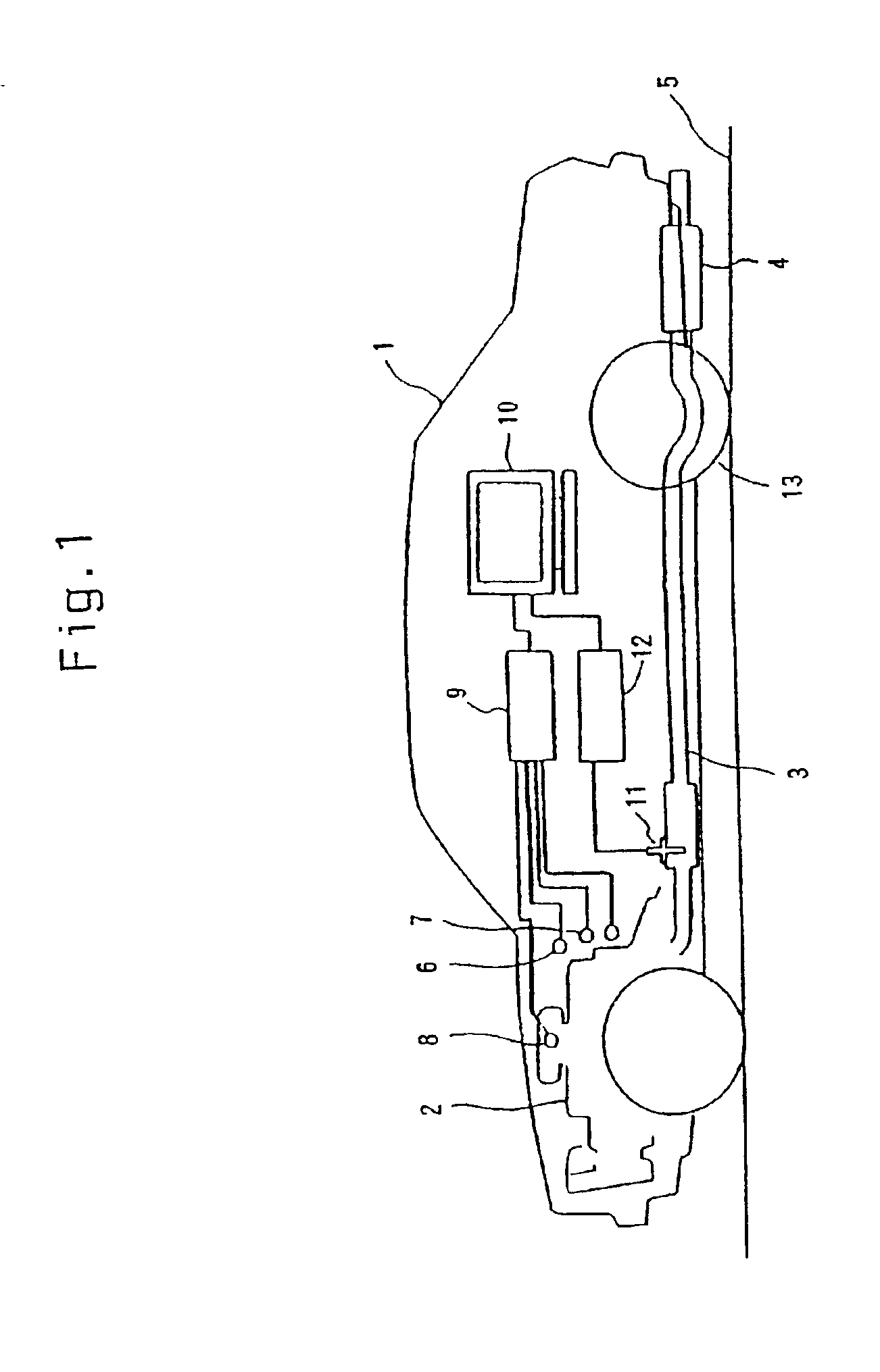
FIG. 1 shows configurations of a method for easily measuring a brake mean effective pressure in accordance with the present invention. In FIG. 1, the reference number 1 represents a vehicle under test. In the exemplary embodiment, the vehicle 1 is a diesel passenger vehicle in which a diesel engine (simply engine, hereinafter) 2 is mounted. Reference number 3 represents an exhaust pipe connected to the engine 2, and reference number 4 represents a muffler provided in the exhaust pipe 3. Reference number 5 represents a road surface.
Reference numbers 6 and 7 represent an engine speed sensor and a vehicle speed sensor, respectively. Reference number 8 represents an air flow sensor (AFS) such as a Kalman flow meter. The AFS 8 is located in an air cleaner (not shown) which is provided in the vicinity of the engine 2. The output of these sensors 6, 7 and the intake air flowmeter 8 are inputted to a microcomputer 10 through an interface 9. The microcomputer 10 is mounted in the vehicle 1 a...
PUM
 Abstract
Description
Claims
Application Information
 - R&D
- Intellectual Property
- Life Sciences
- Materials
- Tech Scout
- Unparalleled Data Quality
- Higher Quality Content
- 60% Fewer Hallucinations
Browse by: Latest US Patents, China's latest patents, Technical Efficacy Thesaurus, Application Domain, Technology Topic, Popular Technical Reports.
© 2025 PatSnap. All rights reserved.Legal|Privacy policy|Modern Slavery Act Transparency Statement|Sitemap|About US| Contact US: help@patsnap.com


