
Machine tool

a technology of machine tools and tools, applied in the field of machine tools, can solve the problems of poor workability and difficult replacement, and achieve the effects of facilitating tool replacement work, preventing scattering of chips and coolant, and improving the workability of tool replacement tasks

Inactive Publication Date: 2005-04-12
DMG MORI SEIKI CO LTD
View PDF18 Cites 10 Cited by
  • Summary
  • Abstract
  • Description
  • Claims
  • Application Information

AI Technical Summary

Benefits of technology

An object of the present invention is to provide a machine tool that allows the tool replacement work to be easily achieved and thereby allows the efficiency of the replacement work to be improved.
In a second aspect of the invention, in the machine tool as described according to the first aspect of the invention, a protector device is provided for preventing chips from scattering between the side wall of the cover and the tool post. A portion of the protector device adjacent the tool post includes an operational opening formed therein and a shutter for opening and closing the operational opening.
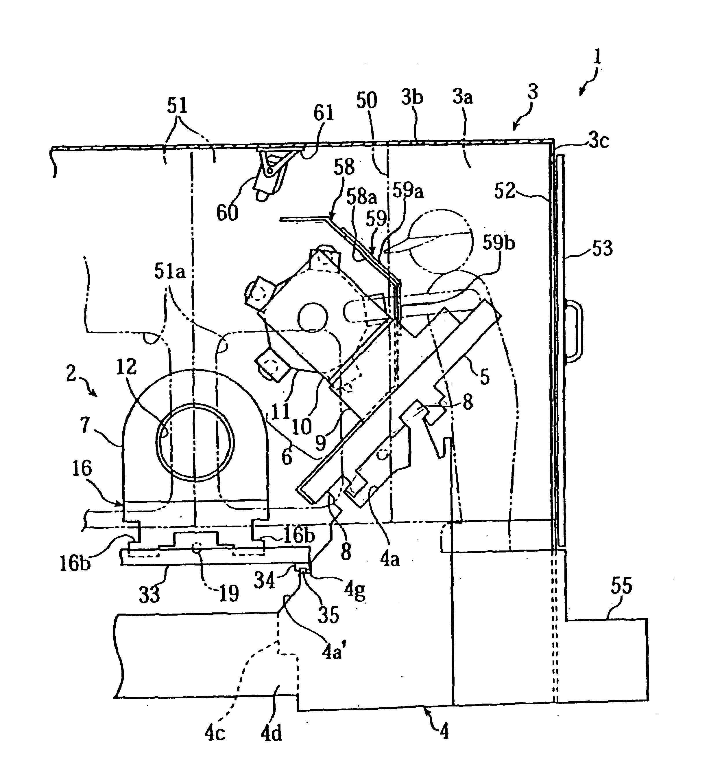
With the machine tool according to the present invention, since the door opening is provided in the side wall of the cover adjacent the tool post, the tool replacement work can be done at a location near the turret head beside the machine body. This means that the tool post body does not interfere with this work and allows the workability of tool replacement task to be improved.
With the machine tool according to the second aspect of the invention, since the protector device provided between the side wall of the cover and the tool post includes an operational opening and the shutter for opening and closing the operational opening, the tool replacement work is facilitated by opening the shutter. Further, during the machining, the scattering of chips and coolant can be prevented by closing the shutter.

Problems solved by technology

In this machine tool, the tool post body interferes with the replacement work, resulting in a difficult replacement with poor workability.

Method used


Image

  • Machine tool
  • Machine tool
  • Machine tool

Examples


Embodiment Construction

Hereinbelow, embodiments of the present invention are described with reference to the accompanying drawings.

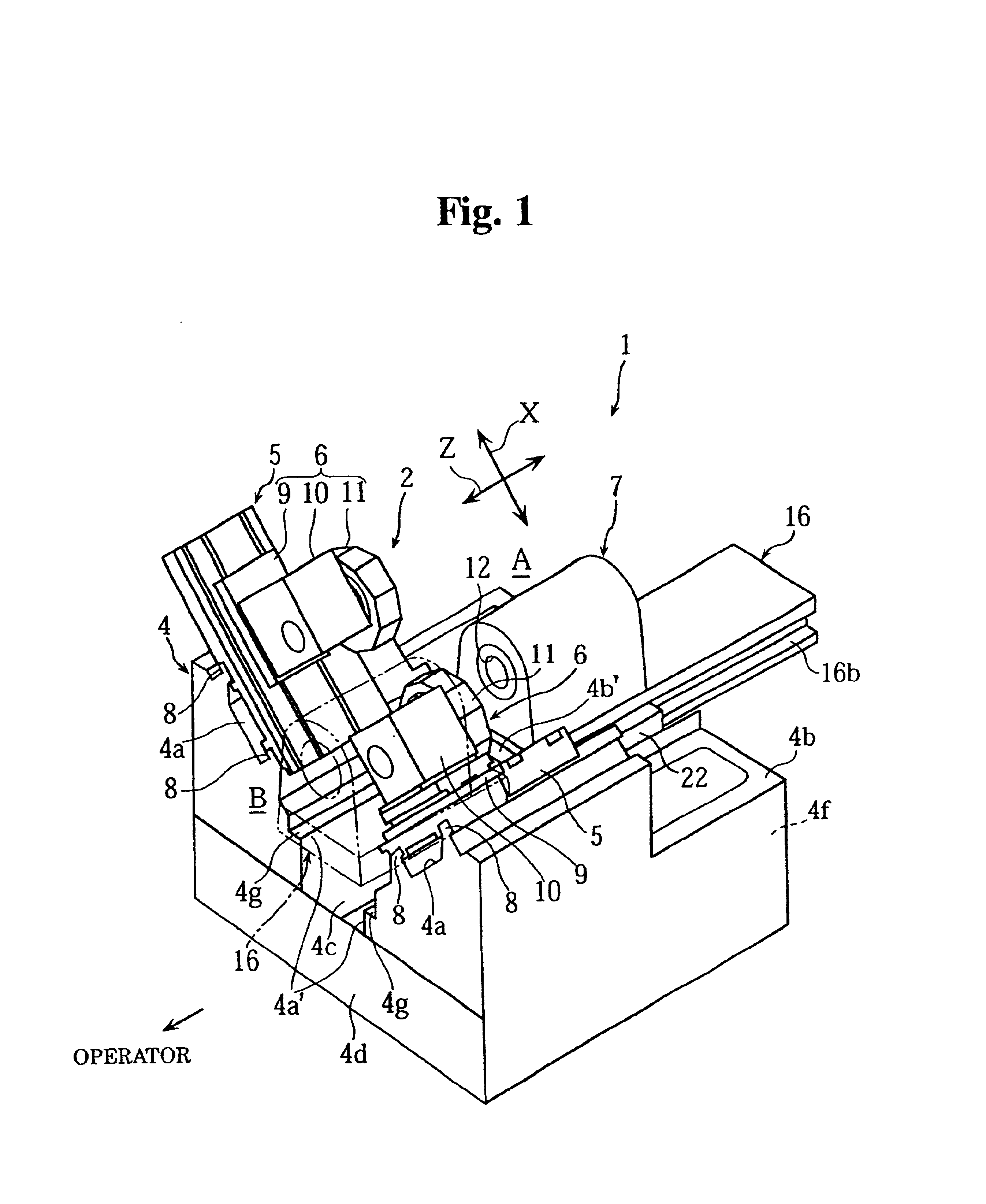
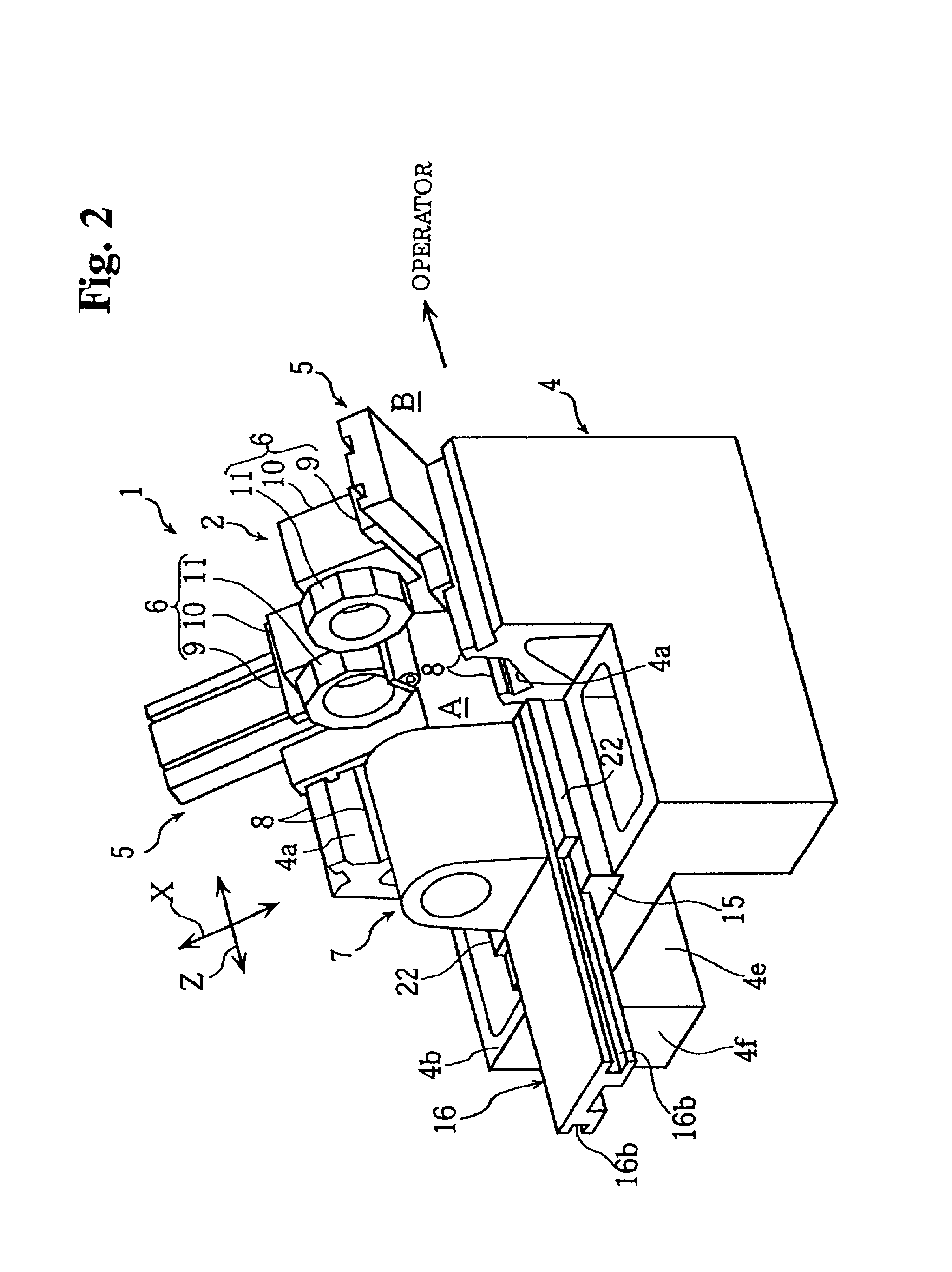
FIGS. 1 through 8 are views for explaining a machine tool (NC lathe) in accordance with the embodiments of the invention. The terms, front and rear, left and right, are referred to in this embodiment as they are viewed from the operator side, that is, the near side means the front, the farther side means the rear, the left side means the left, and the right side means to the right of the operator.

Referring to the figures, reference numeral 1 denotes a machine tool such as an NC lathe that is to be used, for example, to machine aluminum wheels. The NC lathe 1 is constructed so that its machine body 2 is externally surrounded by a cover 3. In this machine body 2, as viewed from the operator, carriages 5 are provided on the left and right sides of a front end portion (on one side nearer the operator) of a fixed bed 4 so as to be movable in a Z-axis direction (back-and-forth direc...


PUM


Abstract

A machine tool such as an NC lathe having a machine body is disclosed. The machine tool comprises a fixed bed, a machine body having a carriage with a tool post mounted thereon is provided on one side of the fixed bed nearer to an operator, and a headstock for loading a workpiece thereon is provided on another side of the fixed bed farther from the operator. The machine tool also includes a cover having a front wall and a side wall to cover at least a front face and a side wall of the machine body, respectively. The cover is provided so as to externally surround the machine tool, and wherein a portion of the side wall of the cover adjacent the tool post includes a door opening formed therein and a side door for opening and closing the door opening. Thus, the tool replacement work is facilitated and the overall workability of the machine tool can be improved.

Description

BACKGROUND OF THE INVENTION1. Field of the InventionThe present invention relates to a machine tool where the machine body is surrounded by a cover. The machine body comprises a tool post disposed on a fixed bed on one side thereof nearer to an operator, and a headstock provided on the other side of the fixed bed farther from the operator on which a workpiece is to be mounted thereon.2. Discussion of the Related ArtConventionally a mass-production type machine tool (such as a Numerically Controlled lathe also called an NC lathe) has carriages with a tool post mounted on each carriage are provided on the left and right sides of the front side (nearer side to the operator) of the fixed bed. A headstock is provided on the rear side (the side farther from the operator) between the two tool posts. In each of the tool posts, a turret head with a plurality of tools mounted thereon is provided on a tool post body so as to be rotationally indexable. In this arrangement, a workpiece mounted o...

Claims


Application Information

Patent Timeline
IPC IPC(8): B23Q11/08B23B3/00B23B3/16
CPCB23B3/167B23Q11/08Y10T409/304088Y10T82/25Y10T82/2508Y10T82/2552Y10T408/98
Inventor NAKAMINAMI, MASAMITSUADACHI, JUN
Owner DMG MORI SEIKI CO LTD
Learn More