Oscillating foil propulsion system

a propulsion system and oscillating foil technology, applied in the field of propulsion systems, can solve the problems of little power consumption of the mechanism or no power at all, and achieve the effect of reducing the lift/drag ratio, increasing the lift, and improving the thrust and efficiency created by the pair of oscillating foil members

Inactive Publication Date: 2005-04-12
NAT RES COUNCIL OF CANADA
View PDF7 Cites 31 Cited by
  • Summary
  • Abstract
  • Description
  • Claims
  • Application Information

AI Technical Summary

Benefits of technology

The present invention operates as well on the principle of “wing-in-ground-effect” (WIG effect), created by the oscillatory movement of the two foil members in counter phase. In aviation parlance, the WIG effect is created when an aerofoil (wing) approaches the ground. It then experiences an increase in lift and a corresponding reduction in the lift/drag ratio. A cushion of air is created between the wing and the groun...

Problems solved by technology

The mechanism may either cons...

Method used


Image

  • Oscillating foil propulsion system
  • Oscillating foil propulsion system
  • Oscillating foil propulsion system

Examples


Embodiment Construction

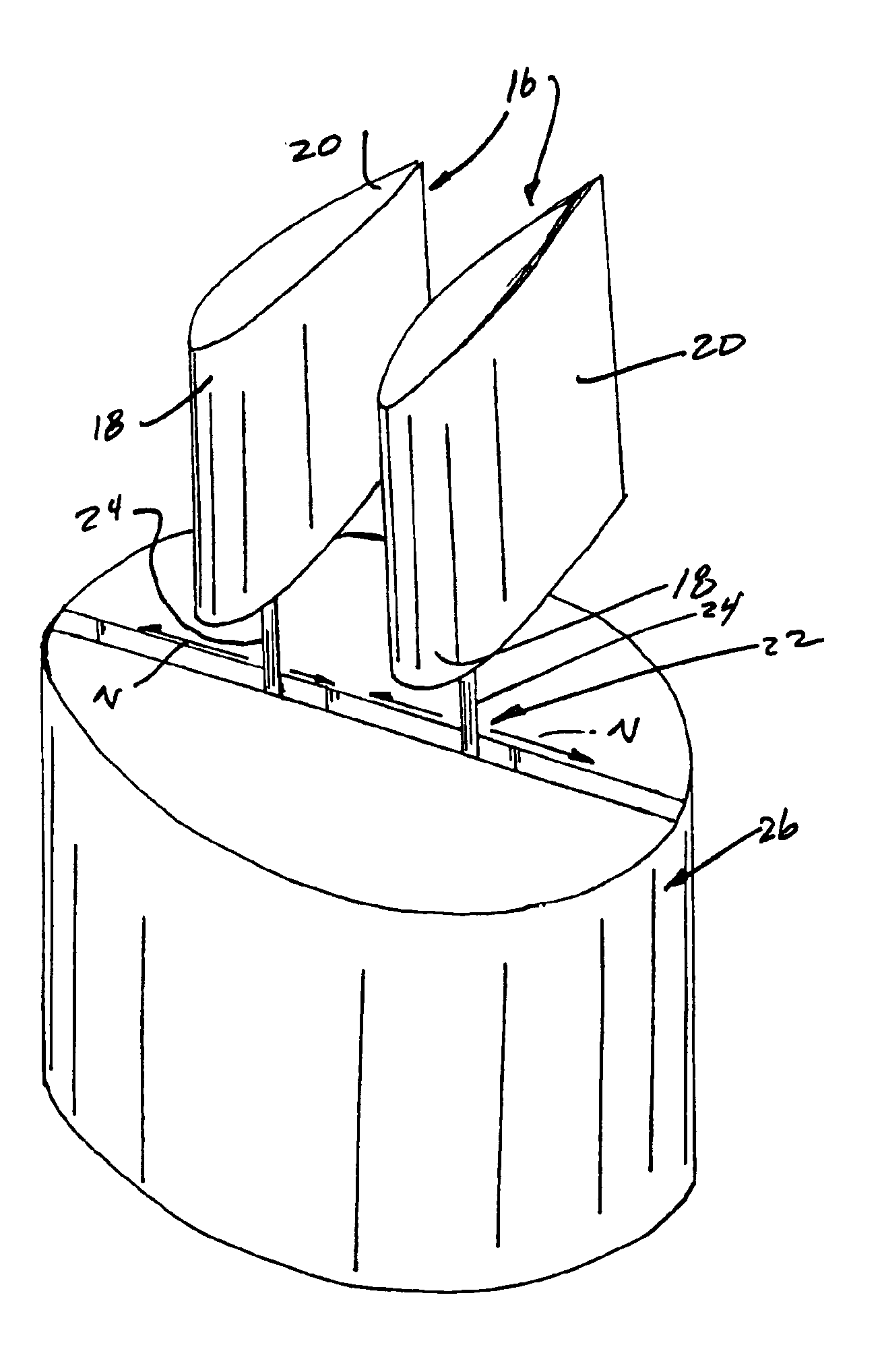
The present invention provides a propulsion system based on the principles of thuniform movement, namely the movement of a foil member in a sideways or vertical manner to achieve forward movement of a vehicle or living body. Such movement is found in nature with fast moving fish or mammals such as tuna, sharks, dolphins and whales. Thuniform movement differs from undulating propulsion systems as used by slower moving fish such as eels. In addition the present invention is based on the principles associated with a “WIG effect” as mentioned hereinabove.

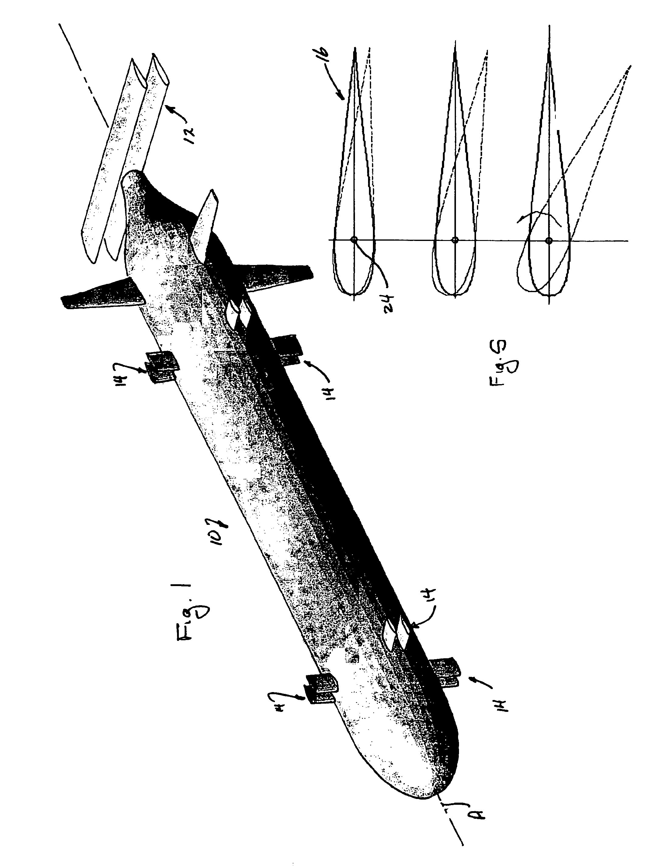
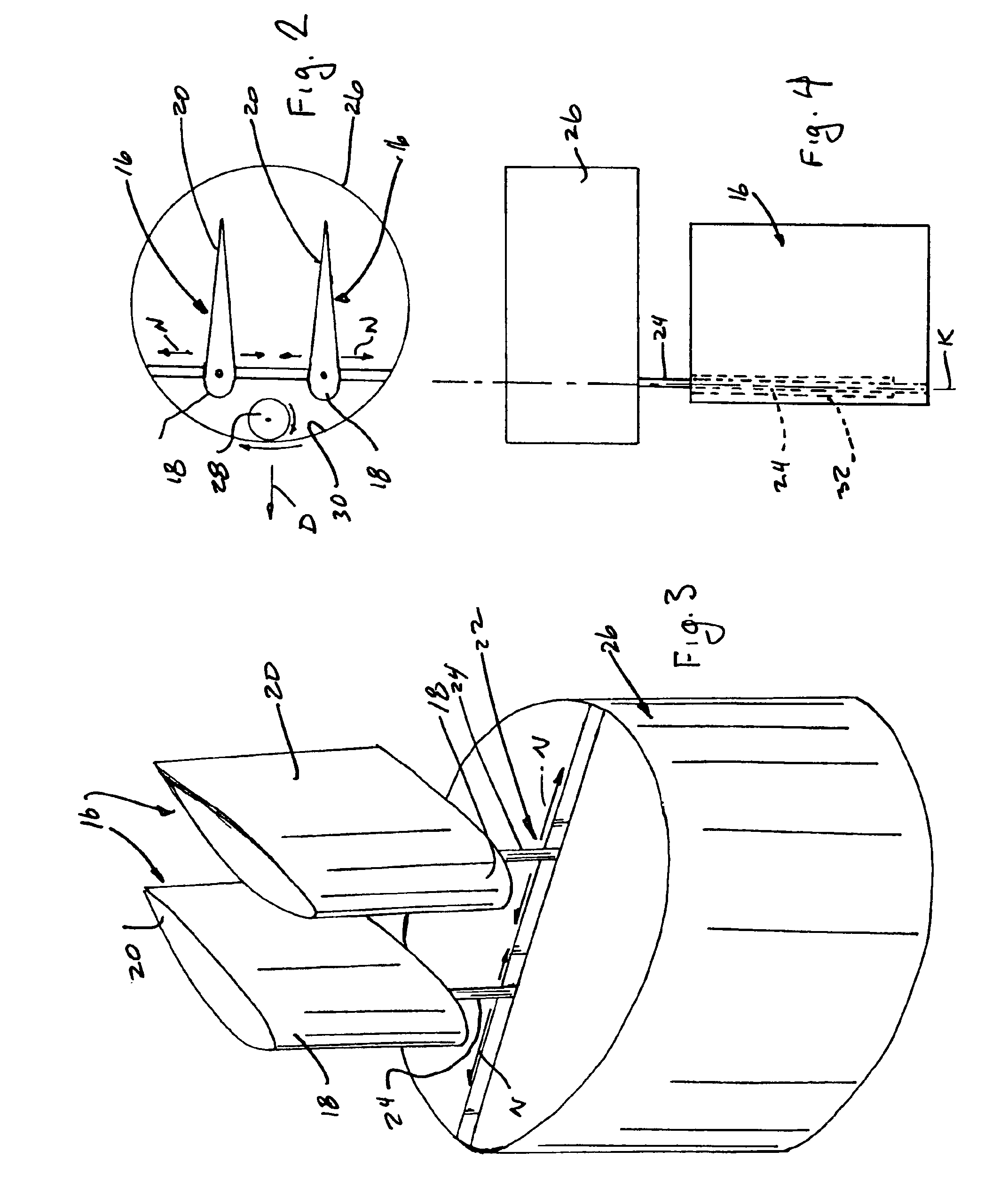
With reference first of all to FIG. 1 a vehicle 10 is shown therein as having a plurality of propulsion systems 12, 14 in accordance with the present invention mounted thereto. The system 12 is provided at the rear end of the vehicle and is intended to impart forward motion only to the vehicle. The systems 14 are mounted to the body of the vehicle and are intended to provide thrust at any angle about the mounting axis thereof, through a...


PUM


Abstract

The invention provides a propulsion system based on “thuniform” movement of a foil member to achieve desired directional movement of a vehicle such as an unmanned submarine type of vessel. A pair of foil members are mounted to the vehicle body for reciprocating oscillating movement towards and away from each other, creating forward movement due to the compression of a fluid medium between the foil members and the expulsion of the compressed fluid rearwardly of the foil members. Each foil member is mounted to a pivot shaft for limited rotational movement with respect to the vehicle body. Damping means are connected between each pivot shaft and its associated foil member so that during operation of the propulsion system damping torque will offset hydrodynamic loads imposed on the foil members by the fluid medium. The damping means will in turn control the pitch angle of the foil members during operation, meaning that a thrust is generated for rigid foil members when moving at zero forward speed. The propulsion system of the invention exhibits increased efficiency and thrust in comparison to other such propulsion systems. The foil members are mounted to the vehicle body in such a manner that the thrust vector thereof can be directed through a full 360 degrees relative to the vehicle, thereby achieving superb maneuverability when the vehicle is provided with sets of the thrusters suitable located thereon.

Description

TECHNICAL FIELD OF THE INVENTIONThis invention relates to propulsion system based on the principle of thuniform motion and is particularly applicable to underwater, and aerial, movement of vehicles. The invention improves on the efficiency and thrust capabilities of prior systems.BACKGROUND OF THE INVENTIONThis invention addresses a problem that has remained unsolved since the first consideration of the concept in the 1960s.John Coxon and Andrew Claughton disclosed the development of an auto-pitch propeller in the publication “The Development of a Self Pitching Propeller System”, (RINA), but the auto-pitch propeller uses the self-pitching technique without any damping torque. This means that each auto-pitch propeller blade rotates about its individual pivot axis freely (only with friction torque that is nearly zero). In operation, the suction side and pressure side of the auto-pitch propeller blades do not alternate.Oscillating or flapping foil propulsors were inspired by the nature...

Claims


Application Information

Patent Timeline
IPC IPC(8): B63H1/36B63H1/00F42B10/00F42B10/64
CPCF42B10/64B63H1/36
Inventor LIU, PENGFEI
Owner NAT RES COUNCIL OF CANADA
Why Eureka
Try Eureka