Multi-stream microfluidic aperture mixers

a microfluidic and mixer technology, applied in the field of mixing and of fluids in microfluidic systems, can solve the problems of high tool-up cost of such techniques, complicated biochemical reactions and processes, and inability to quickly prototyping and manufacture flexibility

Inactive Publication Date: 2005-04-12
AGILENT TECH INC
View PDF77 Cites 76 Cited by
  • Summary
  • Abstract
  • Description
  • Claims
  • Application Information

AI Technical Summary

Benefits of technology

[0015]As is further discussed in the detailed description, microfluidic mixing devices according to different embodiments may be constructed in various differ

Problems solved by technology

In particular, microfluidic systems permit complicated biochemical reactions and processes to be carried out using very small volumes of fluid.
Furthermore, when conducted in microfluidic volumes, a large number of complicated biochemical reactions and/or processes may be carried out in a small area, such as in a single integrated device.
Additionally, these techniques do not lend themselves to rapid prototyping and manufacturing flexibility.
Moreover, the tool-up costs for such techniques are often quite high and can be cost-prohibitive
This method is reported to reduce prototyping time; however, the addition of carbon black renders the material optically impure and presents potential chemical compatibility issues.
Applying conventional mixing strategies to microfluidic volumes is generally ineffective, impractical, or both.
In the laminar regime, using conventional geometric modifications such as baffles is generally ineffective for promoting mixing.
Moreover, the task of integrating moveable stirring elements and/or their drive means in microfluidic devices would be prohibitively difficult using conventional means due to volumetric and/or cost constraints, in addition to concerns regarding their complexity and reliability.
Thus, mixing occurs in such devices very slowly.
One limitation of the disclosed mixing apparatus

Method used


Image

  • Multi-stream microfluidic aperture mixers
  • Multi-stream microfluidic aperture mixers
  • Multi-stream microfluidic aperture mixers

Examples


example 1

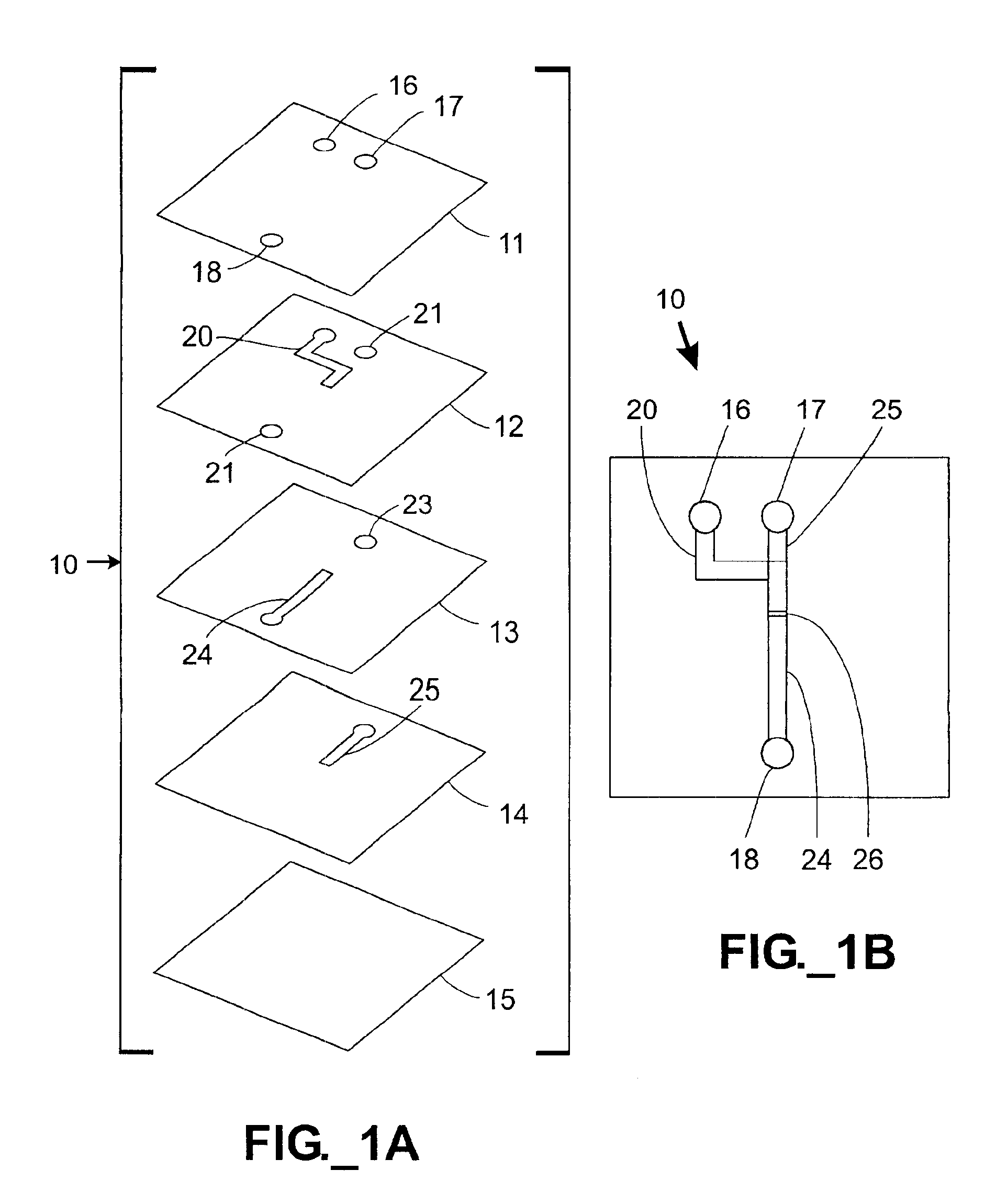
[0085]In this example, the mixing characteristics of various microfluidic mixers according to conventional designs are compared against one microfluidic mixer according to the present invention. Referring to FIGS. 3A-3B, a single device 60 containing four independent microfluidic mixers 90-93 was constructed. The device 60 was constructed from five layers 61-65 (including sandwiched stencil layers 62-64) to demonstrate the novel overlap mixer 90, but the mixers 91-93 approximated conventional 2-dimensional surface micromachined mixers. Applicants are not aware of the construction of conventional mixers such as those illustrated (e.g., mixers 91-93) by others using a sandwiched stencil construction method. The first layer 61 served as a cover layer, defining fluidic inlet ports 66, 67 and outlet ports 70, 71 for each of the three conventional-type mixers 91-93, further defining inlet ports 68, 69 and outlet ports for the novel overlap mixer 90. The second layer 62 defined channels 74...

example 2

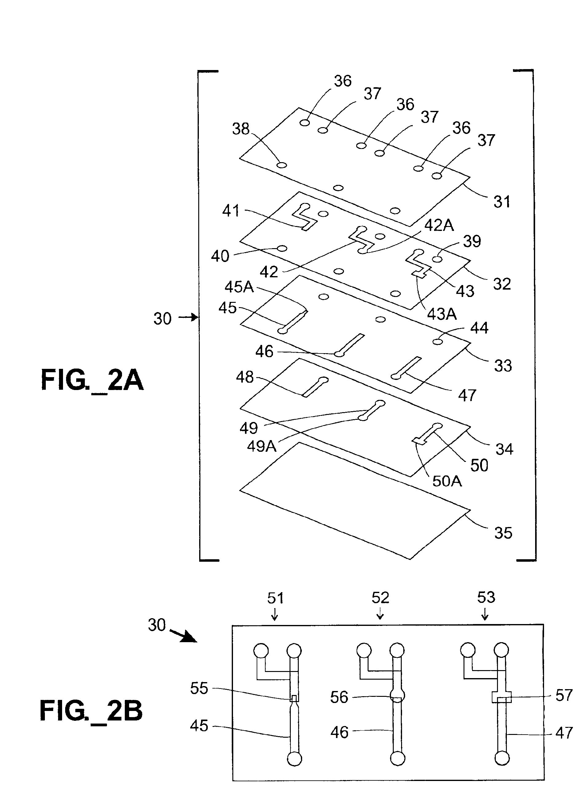
[0092]In one embodiment of the present invention, more than two fluids may be mixed in a single overlap region. For example, FIGS. 5A-5B illustrate a microfluidic mixing device 100 that receives and mixes three different fluid streams. The mixing device 100 is constructed in seven layers 101-107, including stencil layers 102, 104, 106. The first layer 101 defines three fluid inlet ports 108-110 and a single fluid outlet port 112. The second layer 102 defines a first fluid inlet channel 114 and vias 115, 116, 118. The third layer 103 defines three vias 119-121 and a first wide (large) slit 122. The fourth layer 104 defines one via 125 and an inlet / outlet channel 124. The fifth layer 105 defines a via 126 and a second wide slit 127. The sixth layer 106 defines a third fluid inlet channel 128. The seventh layer 107 is a bare substrate that serves as the lower boundary of the channel 128 and serves to support the device 100. All of the channels have a nominal width of about sixty (60) m...

example 3

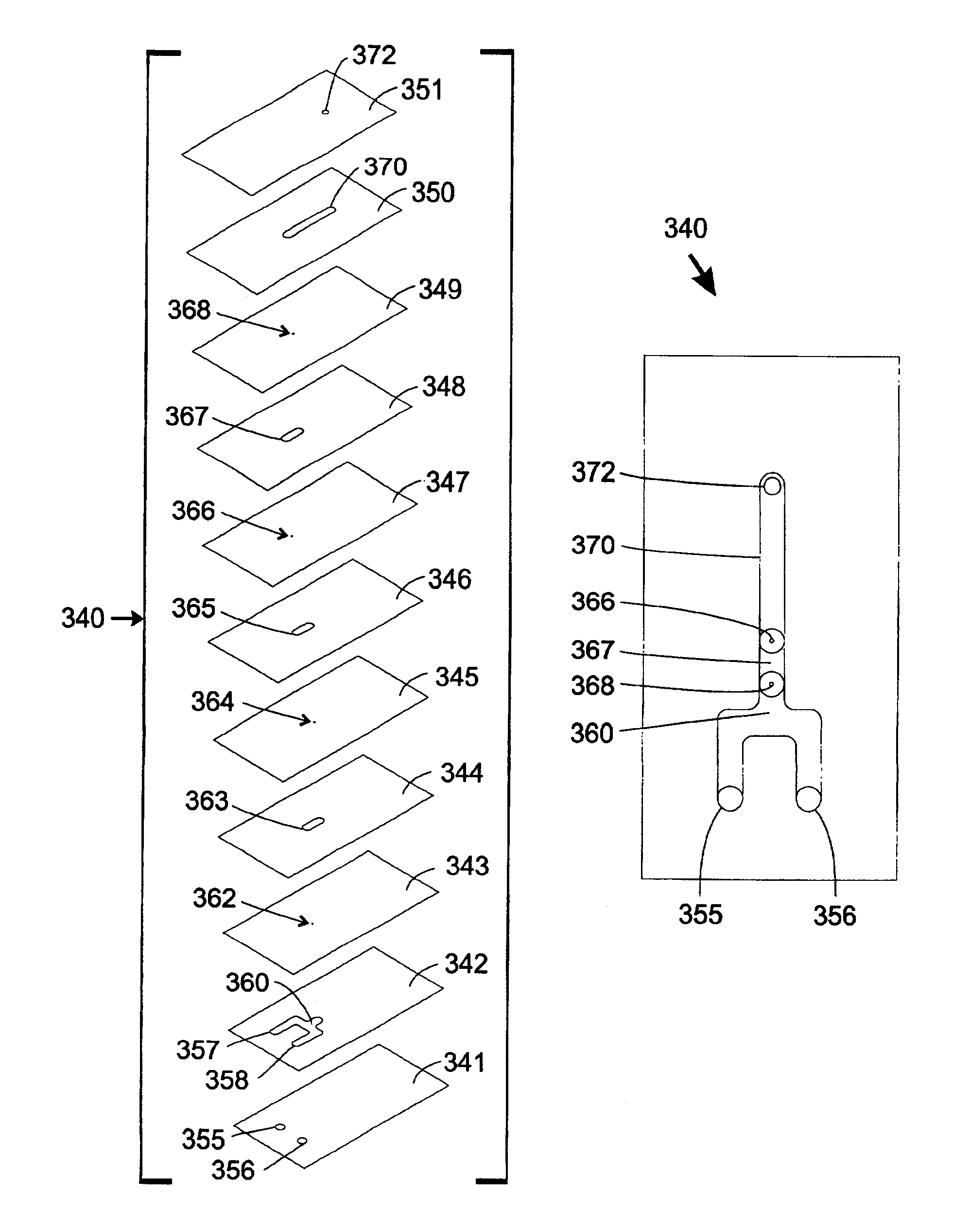
[0094]In one embodiment, multiple fluid input streams may be simultaneously mixed in different proportions to yield a greater number of output streams. For example, a microfluidic multi-mixing device 140 is shown in FIGS. 6A-6B. This mixing device 140 receives two different fluids as inputs and is capable of providing four different fluid streams as outputs. The device 140 is constructed from five layers 141-145, including stencil layers 142-144. The first layer 141 defines two inlet ports 152, 153 and four outlet ports 154-157. The second layer 142 defines vias 158, 159 and five channel segments 160 having rounded portions. The third layer 143 defines two forked inlet channels 162, three intermediate splitting channels 163, and four outlet channels 164. The fourth layer 144 defines five more channel segments 165 having rounded portions. The fifth layer 145 is a bare substrate that encloses the channel segments 165 from below and provides support for the device 140. The forked inlet...


PUM


Abstract

Robust microfluidic mixing devices mix multiple fluid streams passively, without the use of moving parts. In one embodiment, these devices contain microfluidic channels that are formed in various layers of a three-dimensional structure. Mixing may be accomplished with various manipulations of fluid flow paths and/or contacts between fluid streams. In various embodiments, structures such as channel overlaps, slits, converging/diverging regions, turns, and/or apertures may be designed into a mixing device. Mixing devices may be rapidly constructed and prototyped using a stencil construction method in which channels are cut through the entire thickness of a material layer, although other construction methods including surface micromachining techniques may be used.

Description

STATEMENT OF RELATED APPLICATION(S)[0002]This application is filed as a continuation of U.S. patent application Ser. No. 10 / 046,071, filed Jan. 11, 2002 and currently pending.FIELD OF THE INVENTION[0003]The present invention relates to manipulation, and more particularly, mixing, of fluids in microfluidic systems.BACKGROUND OF THE INVENTION[0004]There has been a growing interest in the application of microfluidic systems to a variety of technical areas, including such diverse fields as biochemical analysis, medical diagnostics, chemical synthesis, and environmental monitoring. For example, use of microfluidic systems for acquiring chemical and biological information presents certain advantages. In particular, microfluidic systems permit complicated biochemical reactions and processes to be carried out using very small volumes of fluid. In addition to minimizing sample volume, microfluidic systems increase the response time of reactions and reduce reagent consumption. Furthermore, wh...

Claims


Application Information

Patent Timeline
IPC IPC(8): B01F13/00B01F5/06B01F5/04
CPCB01F5/0471B01F5/0604B01F13/0059B01F5/0646Y10S366/04B01F25/314B01F25/422B01F25/433B01F33/30
Inventor KARP, CHRISTOPH D.
Owner AGILENT TECH INC
Why Eureka
Try Eureka