Heated electrochemical cell
a technology of electrochemical cells and electrochemical solutions, applied in the field of measuring the concentration of analyte in solution, can solve problems such as loss of precision
- Summary
- Abstract
- Description
- Claims
- Application Information
AI Technical Summary
Benefits of technology
Problems solved by technology
Method used
Image
Examples
second embodiment
In the invention the sample is heated electrically, for example by means of a current applied to resistive elements associated with the measuring means.
In a highly preferred embodiment the measuring means is an electrochemical cell of the kind described in co-pending applications PCT / AU96 / 00723 and PCT / AU96 / 00724 and the sample is heated by application of an alternating voltage signal between electrodes of the sensor.
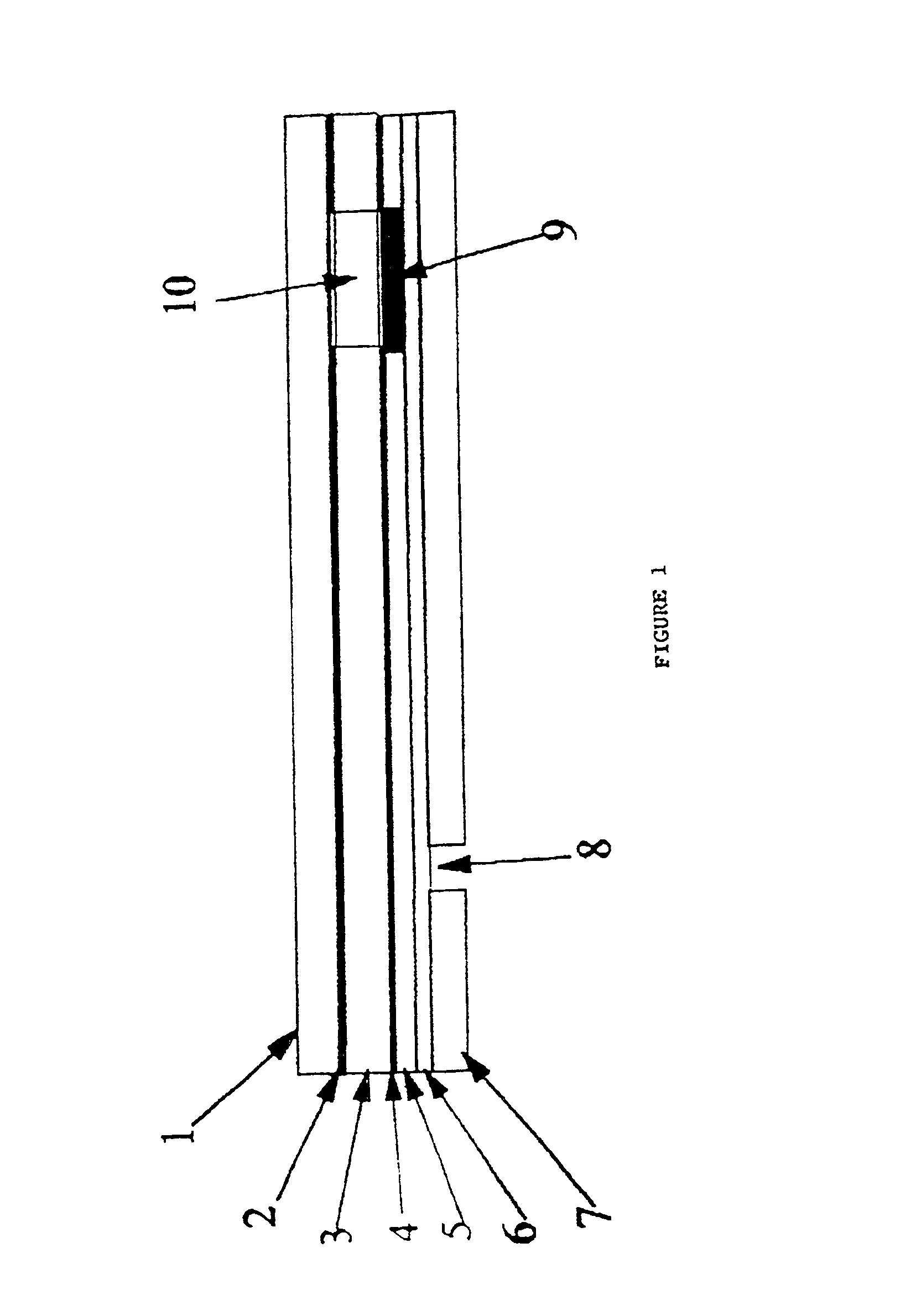
According to a second aspect the invention consists in an electrochemical cell comprising a spacer pierced by an aperture which defines a cell wall, a first metal electrode on one side of the spacer extending over one side of the aperture, a second metal electrode on the other side of the spacer extending over the side of the aperture opposite the first electrode, means for admitting a sample to the cell volume defined between the electrodes and the cell wall, and means for heating a sample contained within the cell.
BRIEF DESCRIPTION OF THE DRAWINGS
The invention will no...
third embodiment
In the invention the sample is heated simply by applying an alternating voltage signal between the working and counter-electrodes of a sensor, for example, of the kind described in our co-pending applications. If this alternating voltage signal has a correct frequency and amplitude it will heat the sample while still allowing an accurate determination of the analyte to be subsequently made by the sensor. Because the voltage signal is alternating any reaction that occurs during one half voltage cycle is reversed during the second half of that cycle, resulting in no net change but in the dissipation of energy that will appear as heat in the sample. This is particularly applicable to sensors of the type disclosed in our abovementioned co-pending patent applications where any small changes that may occur in the cell are quickly removed after interruption of the alternating potential as the cell relaxes back to its initial stage.
When using cells such as described in our co-pending applic...
example 1
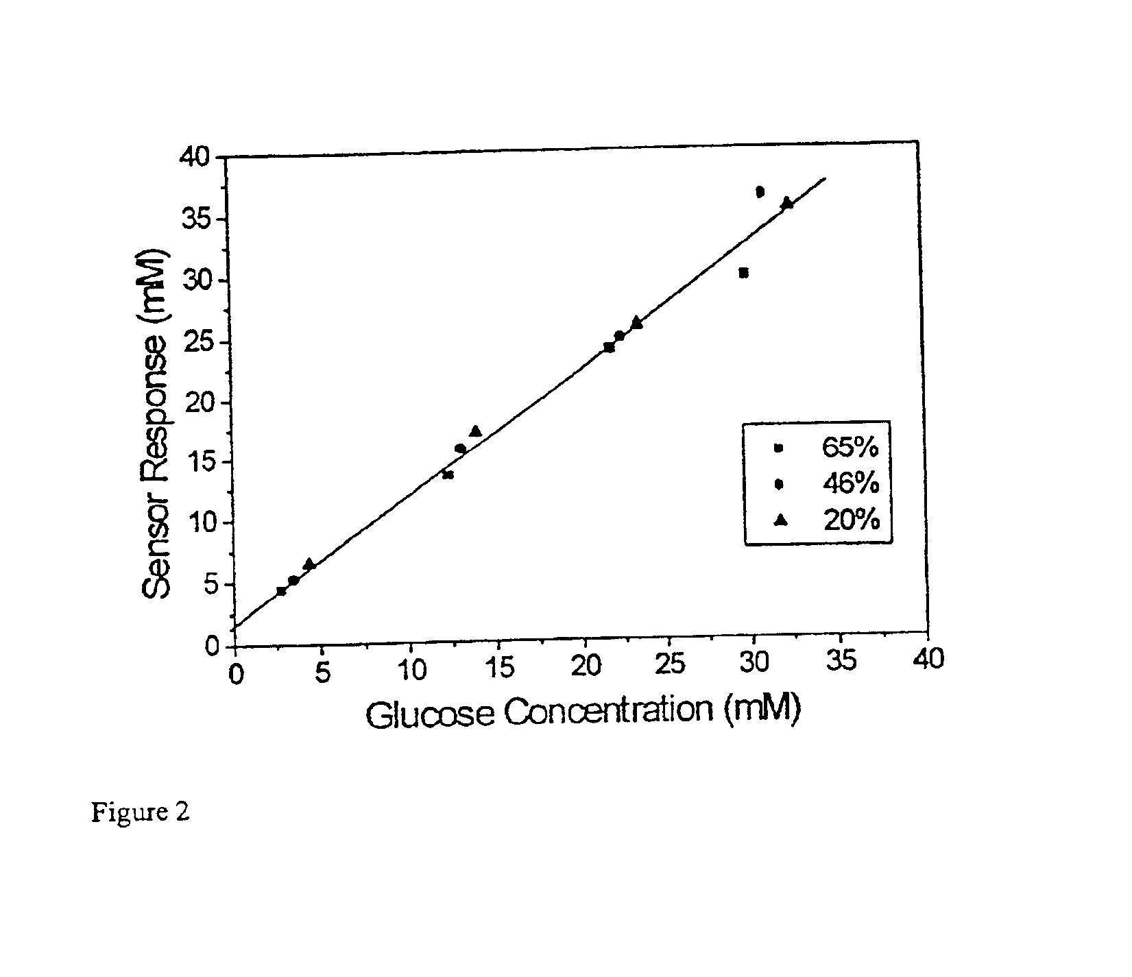
Disposable test strips of the type described in PCT / AU96 / 00724 were heated by placing a metal bar, heated to 50° C., in contact with the sample receiving area of the strip. Whole blood samples were introduced into the sample receiving area of the strip and 13 seconds allowed for the glucose present in the sample to react with the sensor reagents. Current was then collected for ten seconds and analyzed according to the methods described in PCT / AU96 / 00723. The results of these tests for blood samples with haematocrits of 67.5%, 49.5% and 20% and glucose concentrations between 2.5 mM and 30 mM are shown in FIG. 2.
PUM
| Property | Measurement | Unit |
|---|---|---|
| temperature | aaaaa | aaaaa |
| temperature | aaaaa | aaaaa |
| temperature | aaaaa | aaaaa |
Abstract
Description
Claims
Application Information
 - R&D
- Intellectual Property
- Life Sciences
- Materials
- Tech Scout
- Unparalleled Data Quality
- Higher Quality Content
- 60% Fewer Hallucinations
Browse by: Latest US Patents, China's latest patents, Technical Efficacy Thesaurus, Application Domain, Technology Topic, Popular Technical Reports.
© 2025 PatSnap. All rights reserved.Legal|Privacy policy|Modern Slavery Act Transparency Statement|Sitemap|About US| Contact US: help@patsnap.com


