
NOx-concentration measuring apparatus

Inactive Publication Date: 2005-04-12
HORIBA LTD
View PDF11 Cites 47 Cited by
  • Summary
  • Abstract
  • Description
  • Claims
  • Application Information

AI Technical Summary

Benefits of technology

In view of the above circumstances, it is therefore an object of the present invention to provide a NOx-concentration measuring apparatus capable of suppressing NO2 loss due to adsorption and / or dissolution of NO2, thereby accomplishing a high-precision measurement.
The NOx-concentration measuring apparatus constructed as above can suppress NO2 loss due to adsorption and / or dissolution of NO2 to provide a high-precision measurement.
A ratio of the flow rate of the sample gas passing through the drain separator to the internal volume of the drain separator and / or a ratio of the flow rate of the sample gas passing through the drain separator to the internal surface area of a sample-gas passage formed in the drain separator can be increased in a desirable range.

Problems solved by technology

However, the requirement for controlling the concentration of NO2 has not been so strict because NOx in emission gas from a flue or the like generally comprise a large percent of NO and only several percent (5 to 10%) of NO2.
Consequently, the measurement error of NO2 concentration has been a minor concern, and even the factor causing such an error has not been elucidated.
Under these circumstances, the ratio of NO2 to the entire NOx in the flue gas has been increased up to 50% or more in many cases, and thereby the measurement error of NO2 concentration has become a non-negligible issue.
Thus, in the NOx-concentration measuring apparatus disclosed in the above Patent Publication, the first NOx converter located on an upstream side of the dehumidifier can be disadvantageously poisoned by the ammonia, resulting in significantly deteriorated converter efficiency.

Method used


Image

  • NOx-concentration measuring apparatus
  • NOx-concentration measuring apparatus
  • NOx-concentration measuring apparatus

Examples


first embodiment

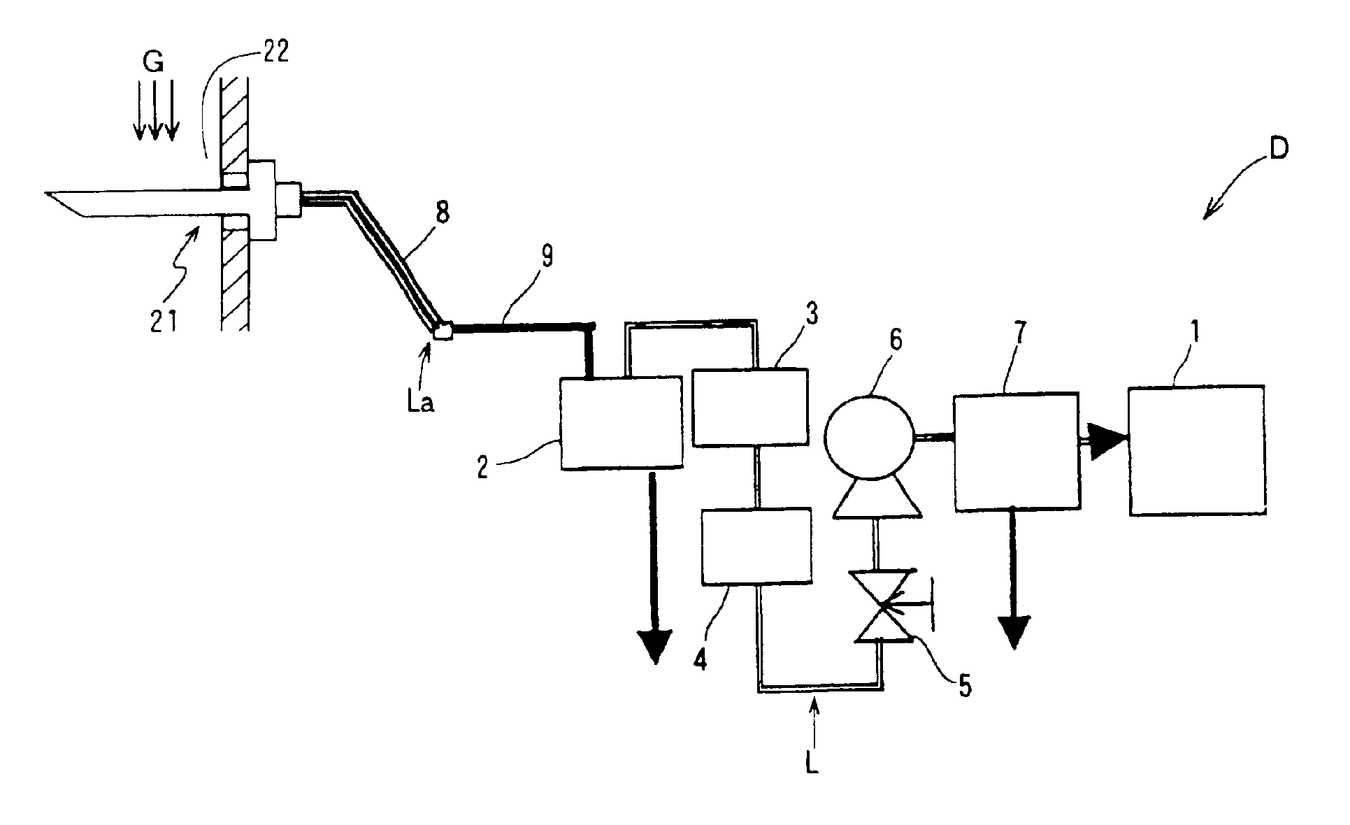
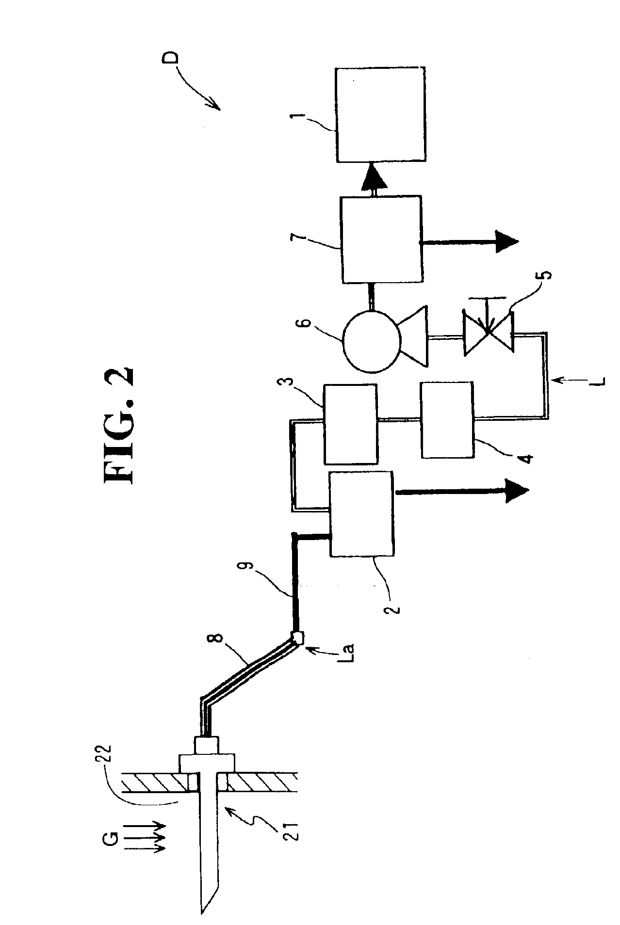
FIG. 1 is a schematic explanatory block diagram showing a NOx-concentration measuring apparatus (hereinafter referred to as “measuring apparatus” for brevity) D according to the present invention.

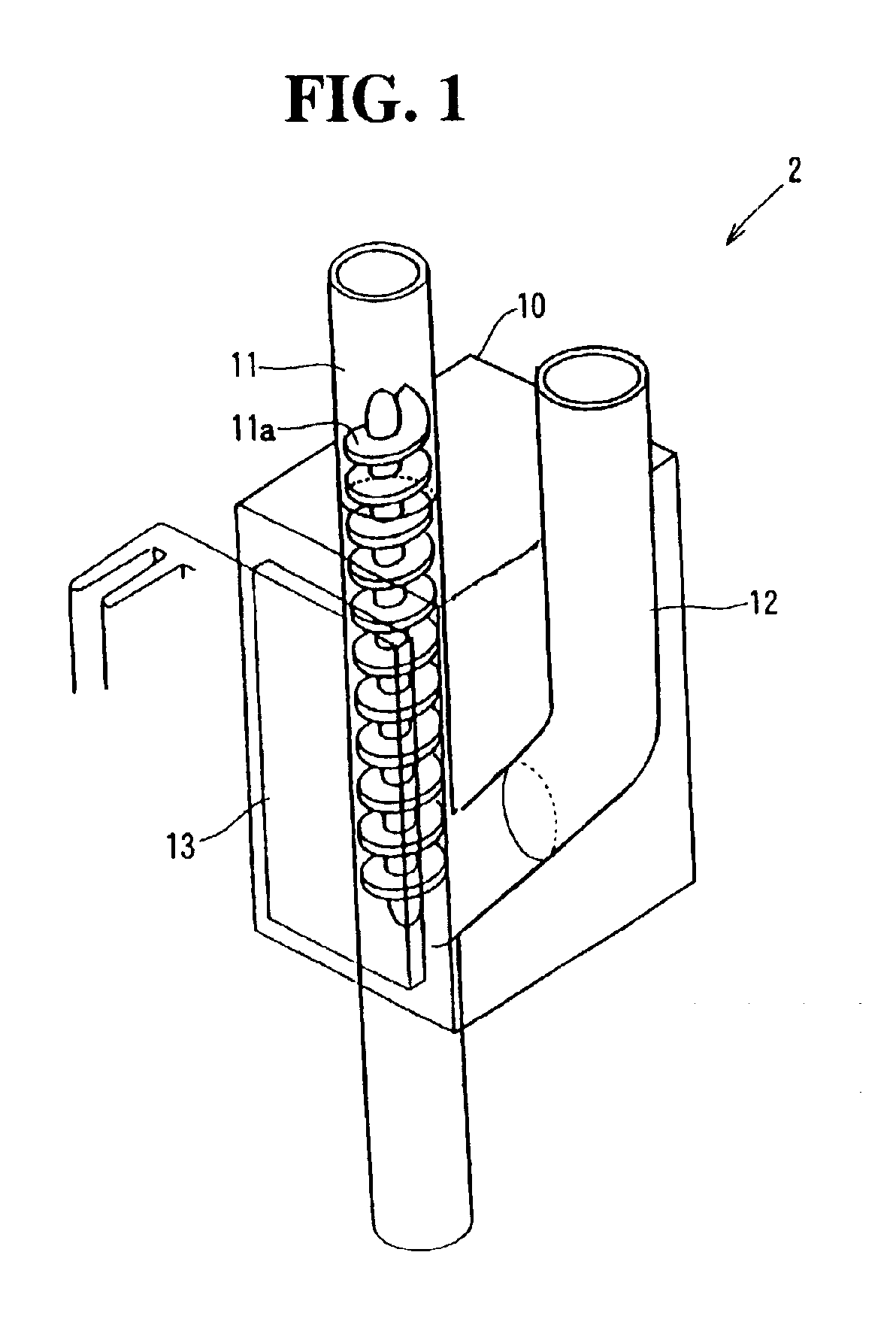
The measuring apparatus D, operable to quantitatively analyze the concentration of NOx contained in a sample gas, comprises a sampling line L for providing fluid communication between a sampling probe 21 for obtaining the sample gas and an NO analyzer 1. Along the sampling line L, the measuring apparatus D further includes a drain separator 2 for condensing the moisture in the sample gas as a condensed water and separating the condensed water from the sample gas, an NO2 converter 3 for converting NO2 contained in the sample gas into NO, a filter 4 for removing a dust contained in the sample gas, a control valve 5 for adjusting the flow volume or flow rate of the sample gas to be passed through the sampling line L, a gas suction pump 6 for making a sample-gas flow from the sampling probe 21 ...


PUM

PropertyMeasurementUnit
Lengthaaaaaaaaaa
Concentrationaaaaaaaaaa
Velocityaaaaaaaaaa

Abstract

The present invention provides a NOx-concentration measuring apparatus D for quantitatively analyzing the concentration of NOx contained in a sample gas. The measuring apparatus D comprises a sampling probe for obtaining the sample gas, a drain separator 2 for condensing moisture contained in the sample gas as a condensed water and separating the condensed water from the sample gas, an NO2 converter 3 for converting NO2 contained in the sample gas into NO, a secondary cooling device 7 for additionally cooling the sample gas, and an NO analyzer 1, arranged in this order with respect to a sample-gas line of the NOx-concentration measuring apparatus. The drain separator is a high-flow-velocity cooling type drain separator.Further, the sample-gas line between the sampling probe and the drain separator is heated and / or thermally insulated over the entire length thereof. The measuring apparatus can provide a high-precision measurement while suppressing NO2 loss.

Description

FIELD OF THE INVENTIONThe present invention relates to a NOx-concentration measuring apparatus used for measuring the concentration of nitrogen oxides (NOx) contained in emission gas from a flue, gas duct or the like.DESCRIPTION OF THE PRIOR ARTFor combustion control in thermal power plants, it is essential, in terms of environmental protection, to suppress the generation of nitrogen oxides (NOx) and to reduce the concentration of unreacted leak ammonia after de-nitration reaction, and it is also essential, in terms of energy saving, to control the injection amount of ammonia for optimizing a denitration process. For this purpose, it is required to measure the concentration of NOx in an emission or flue gas sample taken from a flue. A NOx-concentration measuring apparatus is used in such measurements.Among NOx contained in the flue gas, nitrogen monoxide (NO), due to its stable physicochemical properties, is seldom adsorbed onto the inner wall of pipes of the NOx-concentration measu...

Claims


Application Information

Patent Timeline
IPC IPC(8): B01D5/00G01N33/00G01N1/22
CPCB01D5/0003G01N1/2258G01N33/0037G01N2001/2282Y10T436/25125Y10T436/25875Y10T436/177692Y10T436/178459Y10T436/179228Y02A50/20
Inventor AKIYAMA, SHIGEYUKIINOUE, SATOSHIFUJIWARA, MASAHIKO
Owner HORIBA LTD
Learn More