Method and apparatus for automatic pin detection in microarray spotting instruments

Inactive Publication Date: 2005-04-12
PERKINELMER HEALTH SCIENCES INC
View PDF42 Cites 53 Cited by
  • Summary
  • Abstract
  • Description
  • Claims
  • Application Information

AI Technical Summary

Benefits of technology

A method and apparatus are provided for automatically sensing the presence (or absence) of spot dispensers such as pins in various possible mounting locations in the printhead of a microarray spotting instrument. Pin-location data obtained by the method and apparatus is provided to the computer controller of the instrument, which uses the data to control the motion of the printhead during operation of the instrument. A pin detection apparatus in accordance with t

Problems solved by technology

Solid pins are simple and robust, but in being dipped into the target material in a well typically only take up enough material to form one spot.
As a result of these demanding specifications, the pins are expensive (e.g., a single pin typically costs several hundred dollars).
Also, the pins are very fragile given that the pin tips are so small and precisely shaped.
Since microarrays typically include thousands of spots, using only a single pin to form the microarray would be extremely time consuming.
If a pin gets stuck in the up position, it is not useful for printing.
First, the user might desire a compact pattern of spots in the finished microarray.
Second, the pin spaci

Method used


Image

  • Method and apparatus for automatic pin detection in microarray spotting instruments
  • Method and apparatus for automatic pin detection in microarray spotting instruments
  • Method and apparatus for automatic pin detection in microarray spotting instruments

Examples


Embodiment Construction

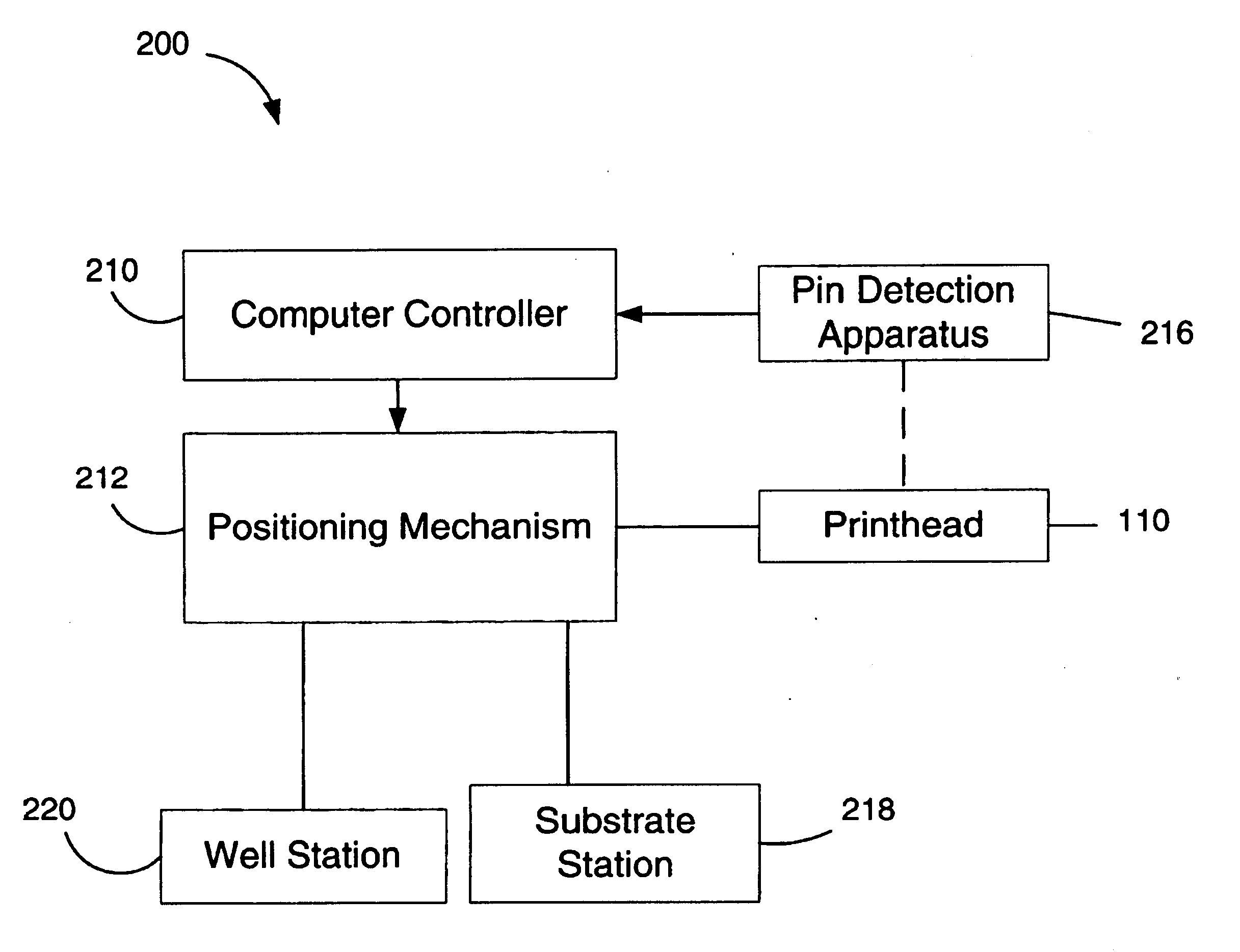
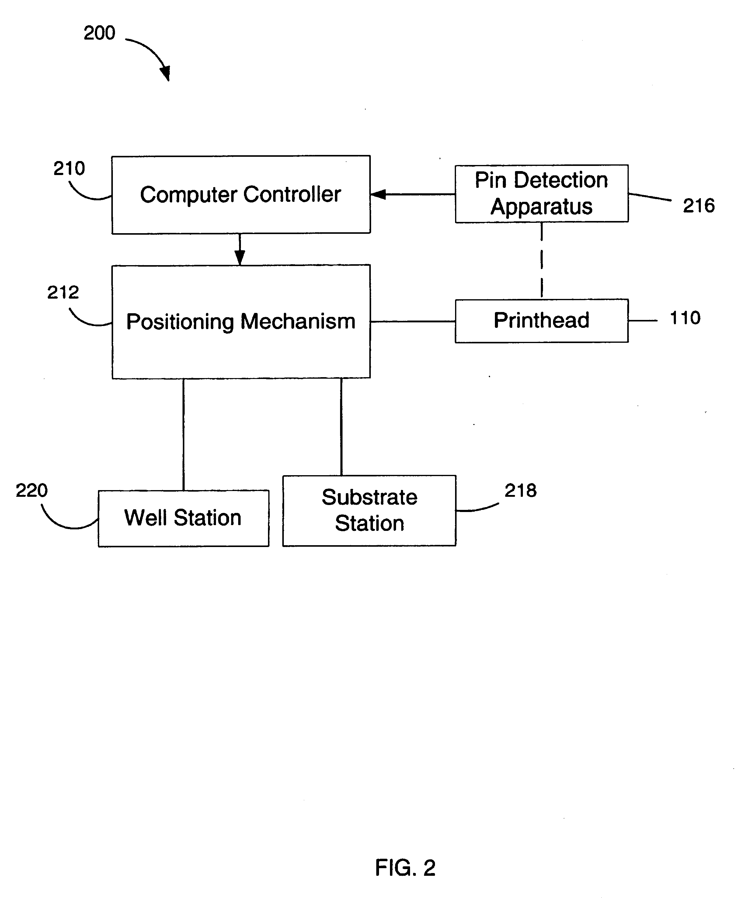
The present invention is generally directed to a method and apparatus for automatically sensing the presence (or absence) of spot dispensers such as pins in various possible mounting locations in the printhead of a microarray spotting instrument. Pin-location data obtained by the method and apparatus is provided to the computer controller of the instrument, which uses the data to control the motion of the printhead during operation of the instrument. More specifically, the controller utilizes the pin location data to determine the proper positioning coordinates for the printhead in subsequent sample uptake and microarray spot printing operations for one or more of microarrays being printed. Pin sensors can also report an error condition to a user.

Pin location sensing in accordance with the invention can be performed as needed at any time during use of the instrument. However, the inventive system is particularly useful for automating the initialization process of microarray spotting...


PUM


Abstract

A method and apparatus are provided for automatically sensing the presence (or absence) of spot dispensers such as pins in various possible mounting locations in the printhead of a microarray spotting instrument. Pin-location data obtained by the method and apparatus is provided to the computer controller of the instrument, which uses the data to control the motion of the printhead during operation of the instrument. A pin detection apparatus includes one or more sensor elements that automatically sense possible pin locations in the printhead for the presence of pins. The sensor elements are preferably arranged in an array corresponding to the array of pin locations in the printhead so that pin detection at each pin location can be performed simultaneously. Various types of sensor elements can be used to locate pins in a printhead. For example, sensors can be used that are remote from or attached to a printhead. Pin sensors can be used that sense pin locations from various positions relative to the printhead including above or below the printhead. Also, pin sensing can be by contact or non-contact mechanisms. The method and apparatus allow pin positions in a printhead to be quickly and accurately determined, and without significant risk of damaging the pins, which are fragile.

Description

BACKGROUND OF THE INVENTION1. Field of the InventionThe present invention relates generally to microarray spotting instruments and, more particularly, to a method and apparatus for detecting the presence of pins at particular locations in a printhead of such instruments.2. Description of Related ArtAs is well known (and described, e.g., in U.S. Pat. No. 5,807,522 issued to Brown et al. and in “DNA Microarrays: A Practical Approach,” Schena, Mark, New York, Oxford University Press, 1999, ISBN 0-19-963776-8), microarrays are arrays of very small samples of purified DNA or protein target material arranged as a grid of hundreds or thousands of small spots on a solid substrate. When the microarray is exposed to selected probe material, the probe material selectively binds to the target spots only where complementary bonding sites occur, through a process called hybridization. Subsequent quantitative scanning in a fluorescent microarray scanner may be used to produce a pixel map of fluore...

Claims


Application Information

Patent Timeline
IPC IPC(8): B01L3/02B01J19/00G01N33/53C40B60/14G01N37/00
CPCB01J19/0046B01L3/0244B82Y30/00Y10T436/119163B01J2219/00527B01J2219/00585B01J2219/0059B01J2219/00596B01J2219/00605B01J2219/00612B01J2219/00621B01J2219/00637B01J2219/00659B01J2219/00677B01J2219/00689B01J2219/00693B01L3/0241C40B60/14Y10T436/114998Y10T436/11Y10T436/2575B01J2219/00387
Inventor SCHERMER, MACK J.CANDILORO, C. BRIAN
Owner PERKINELMER HEALTH SCIENCES INC
Why Eureka
Try Eureka