Stator coil assembly for superconducting rotating machines

a superconducting rotating machine and coil assembly technology, which is applied in the direction of windings, cooling/ventilation arrangement, magnetic circuit shape/form/construction, etc., can solve the problems of high dispersion, increase of magneto motive forces generated by windings, and increase of machine flux densities, so as to facilitate cooling

Inactive Publication Date: 2005-04-12
AMERICAN SUPERCONDUCTOR
View PDF7 Cites 32 Cited by
  • Summary
  • Abstract
  • Description
  • Claims
  • Application Information

AI Technical Summary

Benefits of technology

The stator support system forms a structural box about the individual stator coil windings to resist movement and deformation due to the tremendous forces generated by the stator coil under operation. The structural box retains the diamond pattern of each stator coil winding and provides a mechanical link between the stator coil and the housing of the superconducting motor. The torque generated by the stator coil is transferred, via this mechanical link to the housing and, in turn, to the foundation of the superconducting motor for structural support. The support provided by these structural boxes results in less internal movement of the stator coil and, over the lifetime of the superconducting motor, reduces degradation of the ground plane insulation, thereby minimizing electrical failure.
An electrically insulating material wrapped around each stator coil insulates the stator coil. A cooling conduit is then mounted adjacent to the stator coil, in thermal contact with the electrically insulating material. The cooling conduit receives a coolant from an outside source. Because the cooling conduit is electrically isolated from the stator coil, fresh water can be used. Fresh water is advantageous in situations where de-ionized water is not available or costly to carry.
The cooling conduit and stator coil are then wrapped with a thermally conductive member. The thermally conductive member facilitates cooling from around the entire stator coil. Absent the thermally conductive member, heat transfer would occur only at the contact point between the cooling conduit and the electrically insulating material causing a thermal gradient in the electrically insulating material. A thermal gradient would cause premature electrical failure in the electrically insulating material, and, therefore, premature failure of the stator assembly.
In certain embodiments, varying the thickness of the electrically insulating material may further enhance the cooling conduits. The voltage within the stator assembly varies depending on a stator coil's placement within the stator assembly. The electrically insulating material does not have to be as thick at lower voltages. Therefore, the thickness can be varied proportionally to the voltage experienced at any given stator coil. The maximum thickness will be nearest the line voltage potential, and the minimum thickness will be nearest the ground potential.

Problems solved by technology

The use of superconducting windings in these machines has resulted in a significant increase in the magneto motive forces generated by the windings and increased flux densities in the machines.
These machines operate without iron teeth between the stator coils since the flux density would result in high dissipation in these members.

Method used


Image

  • Stator coil assembly for superconducting rotating machines
  • Stator coil assembly for superconducting rotating machines
  • Stator coil assembly for superconducting rotating machines

Examples


Embodiment Construction

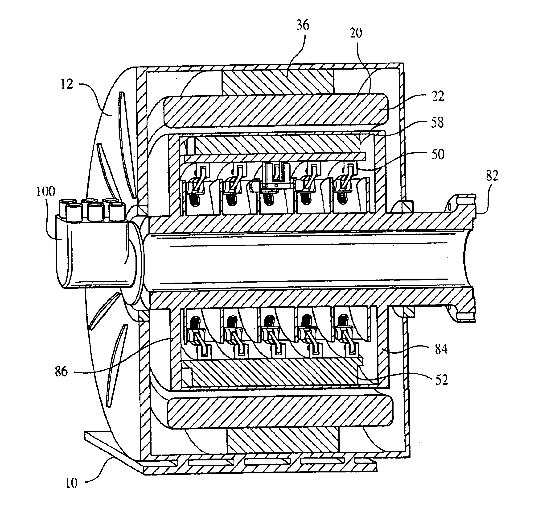
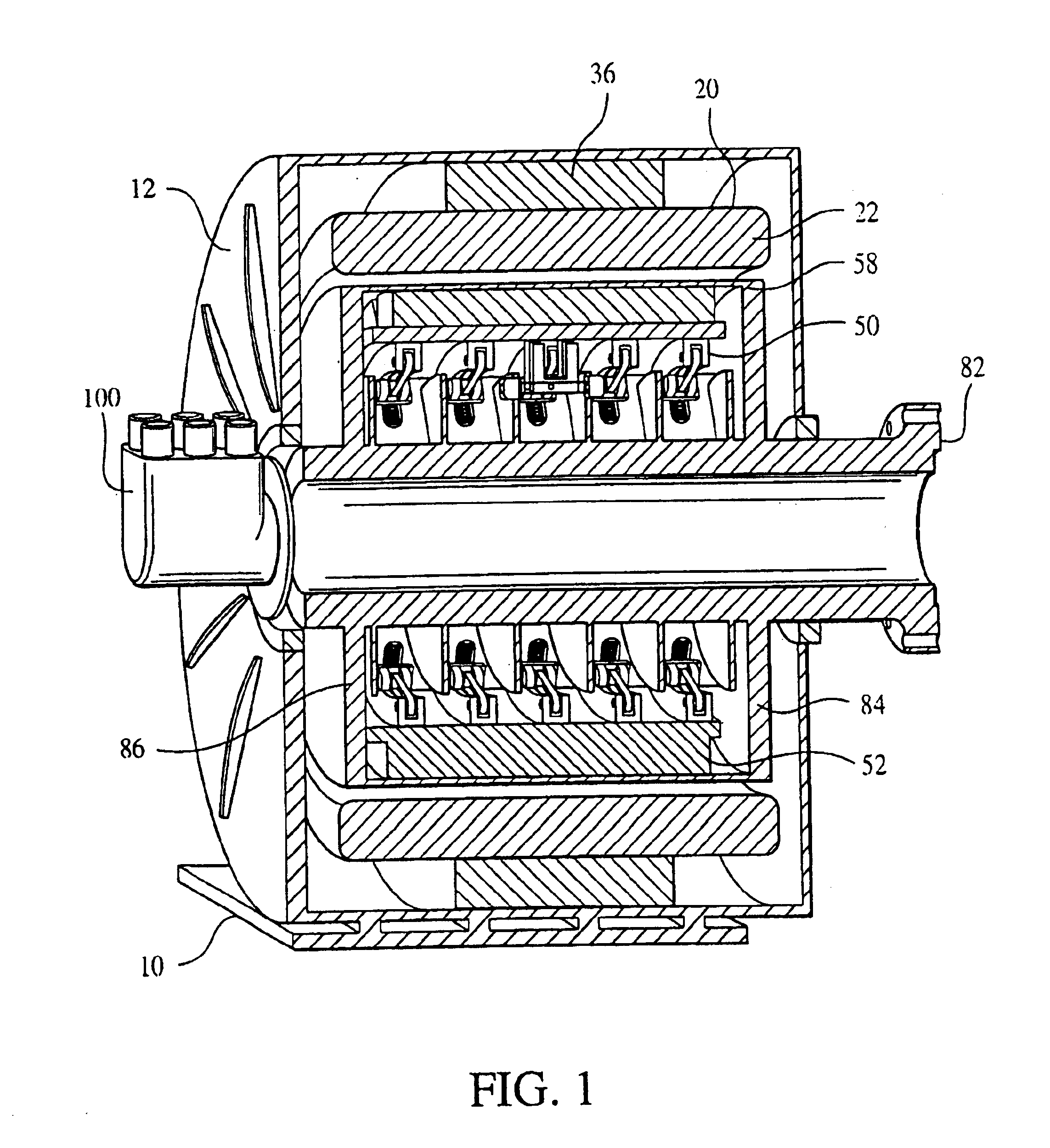
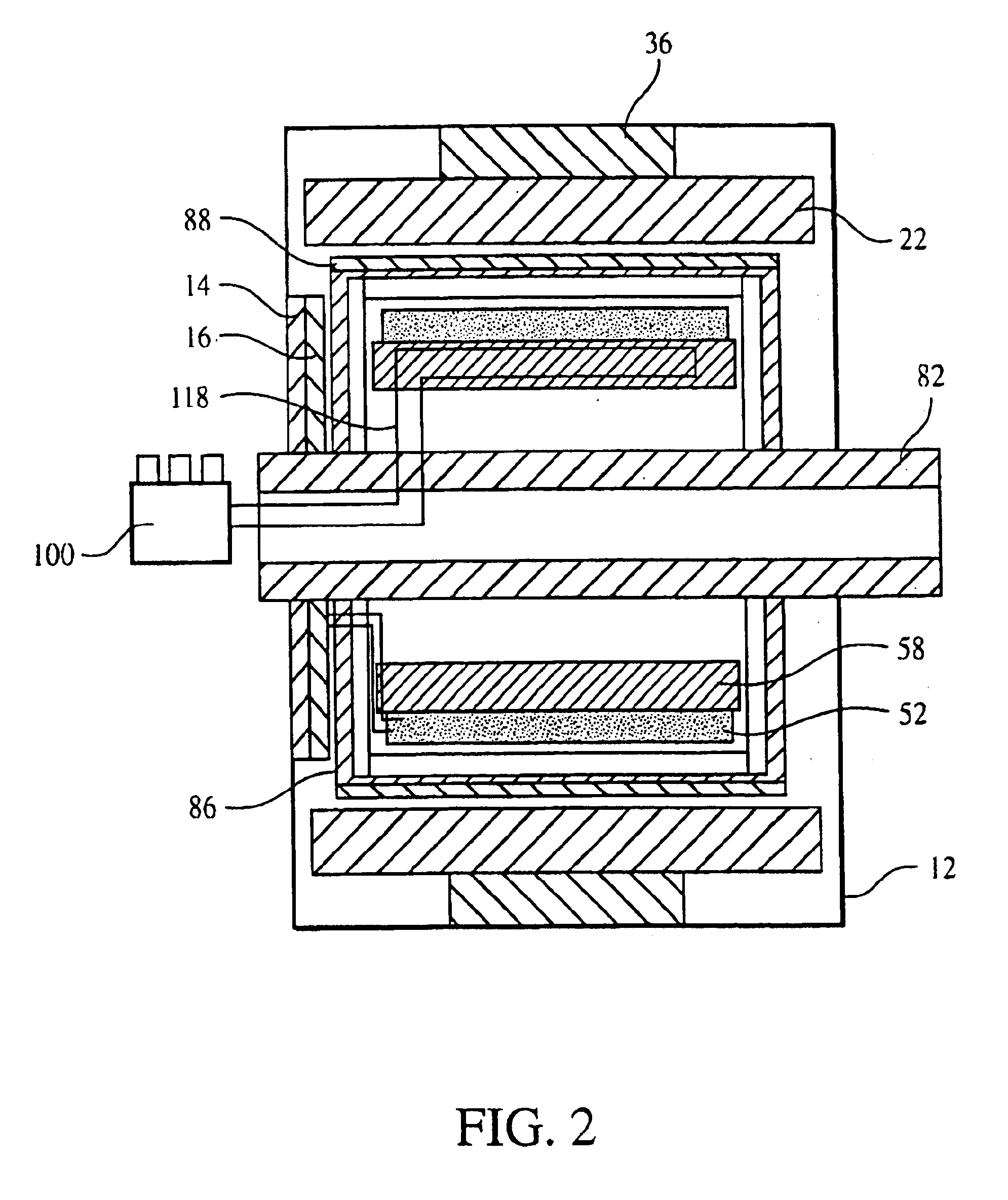
Referring to FIGS. 1 and 2, a superconducting synchronous motor 10 includes a rotor assembly 50 cooled by a cryogenic cooling system 100, here a Gifford McMahon (GM) cooling system, and surrounded by a stator assembly 20. Both the stator assembly 20 and the rotor assembly 50 are mounted in a housing 12 to protect the components and any users of the superconducting motor 10 and to transmit motor torques to the mounting foundation. As will be described in greater detail below, each of these components and assemblies have features which contribute toward both increasing the overall performance, as well as reducing the overall size of motor 10. In particular, superconducting synchronous motor 10 can be shown to produce torque densities as high as 75 Nm / Kg or more at 500 RPM or less. Furthermore, such motors are expected to provide a greatly improved gap shear stress characteristic in a range between 15 psi and 100 psi.

Referring to FIGS. 1 and 3-5, the stator assembly 20 includes, in thi...


PUM


Abstract

A stator support system for supporting a stator coil assembly includes a inner support tube having an outer surface; spaced windings supported on the inner support tube with spaces between adjacent windings defining gaps; support members, each disposed within one of the gaps and having a first and second edge configured to mechanically engage the outer surface of the inner support tube; and a cross support positioned over the spaced winding and extending perpendicular to a longitudinal axis of the stator coil assembly. The cross support having a first edge configured to mechanically engage the second edge of the support members. The stator coil assembly can include a stator coil having at least one conductive winding; an electrically insulating material disposed around the stator coil; at least one cooling conduit for receiving a coolant from an outside source, the at least one cooling conduit disposed adjacent a first portion of an outer surface of the stator coil; and a thermally conductive member including graphite and disposed around the at least one cooling conduit and a second portion of the outer surface of the stator coil to transfer heat from the second portion to the at least one cooling conduit, thereby reducing the temperature gradient in the electrically insulating material.

Description

TECHNICAL FIELDThis invention relates to the construction and operation of superconducting rotating machines, and more particularly to stator construction for use in superconducting motors.BACKGROUNDSuperconducting air core, synchronous electric machines have been under development since the early 1960s. The use of superconducting windings in these machines has resulted in a significant increase in the magneto motive forces generated by the windings and increased flux densities in the machines. These machines operate without iron teeth between the stator coils since the flux density would result in high dissipation in these members. In conventional machines, the coils are surrounded by a laminated stack of iron that acts as a flux path. The laminated stack includes teeth that extend between the coils to provide a flux path and to support the coils. In a superconducting machine a system is required for supporting large loads on the coils that does not have high losses in a large alte...

Claims


Application Information

Patent Timeline
Patent Type & Authority Patents(United States)
IPC IPC(8): H02K55/00H02K3/24H02K3/46H02K55/02H02K3/04H02K3/47H02K9/22
CPCH02K3/24H02K3/47H02K55/04Y02E40/625H02K9/22Y02E40/60H02K9/227
Inventor HOWARD, RAYMOND T.GAMBLE, BRUCE B.WINN, PETER M.SAND, WILLIAM T.KALSI, SWARN S.
Owner AMERICAN SUPERCONDUCTOR
Why Eureka
Try Eureka