Lithographic apparatus and device manufacturing method

a technology of lithographic apparatus and manufacturing method, which is applied in the direction of electrical apparatus, printers, instruments, etc., can solve the problems of difficult to get a partially hydrocarbon pressure below, material types are often deleterious to the vacuum, and their use is impractical, so as to reduce the problem

Inactive Publication Date: 2005-04-12
ASML NETHERLANDS BV
View PDF8 Cites 16 Cited by
  • Summary
  • Abstract
  • Description
  • Claims
  • Application Information

AI Technical Summary

Benefits of technology

[0018]It is an aspect of the present invention to provide a lithographic projection apparatus with substantially reduced problems due to out-gassing of materials used in a conduit in a vacuum chamber.

Problems solved by technology

However, these types of materials often are deleterious to the vacuum in the vacuum chamber because out-gassing of contaminants as described above will occur.
It will be difficult to get a partially hydrocarbon pressure below 10−8 or 10−9 millibar, for example, when plastic conduits are used.
Furthermore, the risk of leaks from conduits makes their use impractical.
However, conventional designs of substrate, mask and transfer stages are very complicated and employ large numbers of sensors and drive arrangements, which all need a large number of conduits for conveying water and gases and for protecting electric wiring.
A disadvantage of the joints is that it is very difficult to design joints that are totally closed for fluids or gases in a vacuum environment.
Therefore there may be leakage of gases through the joint to the vacuum environment that will contaminate the vacuum environment.

Method used


Image

  • Lithographic apparatus and device manufacturing method
  • Lithographic apparatus and device manufacturing method
  • Lithographic apparatus and device manufacturing method

Examples


Embodiment Construction

ich:

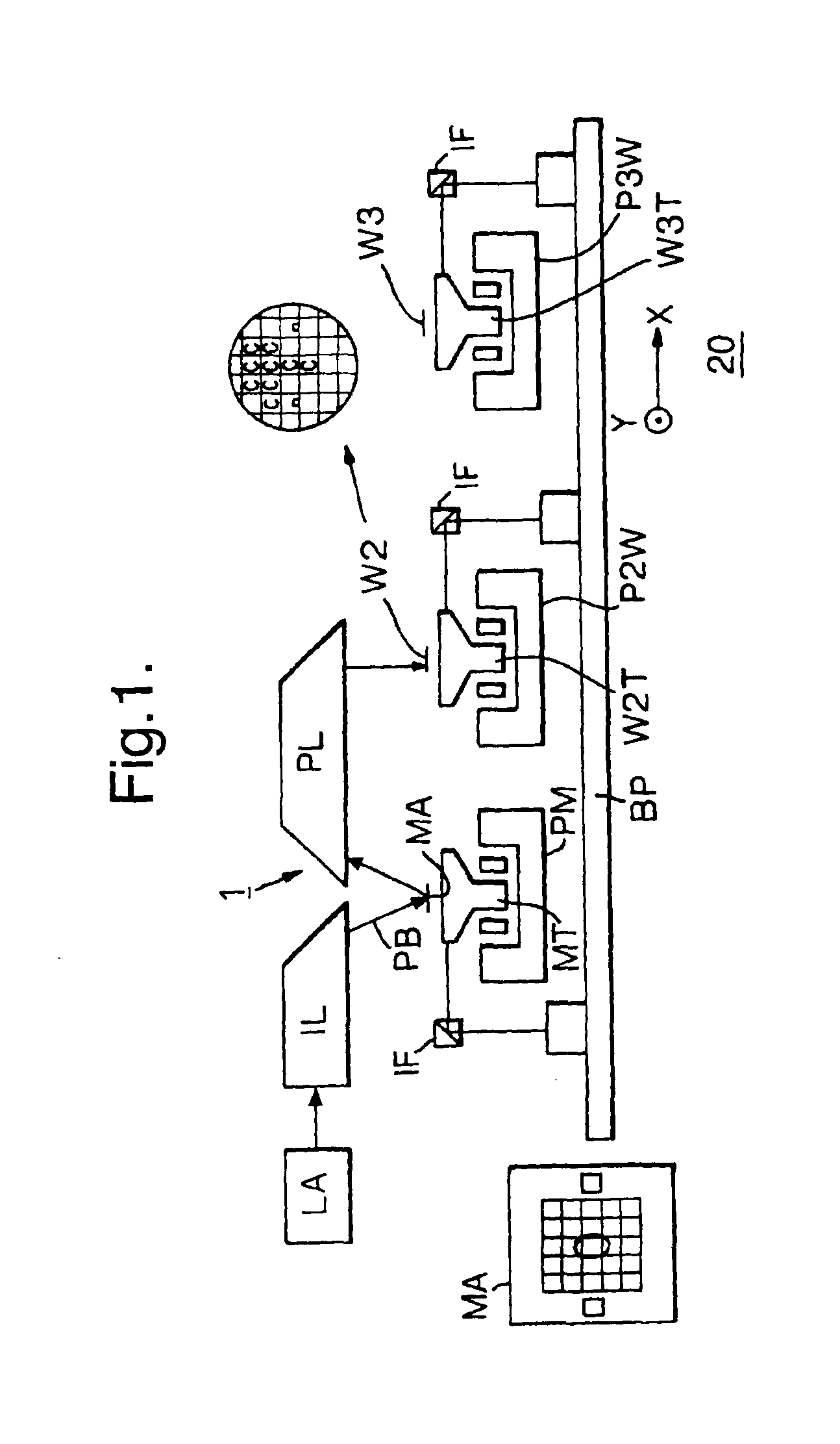
[0027]FIG. 1 depicts a lithographic projection apparatus;

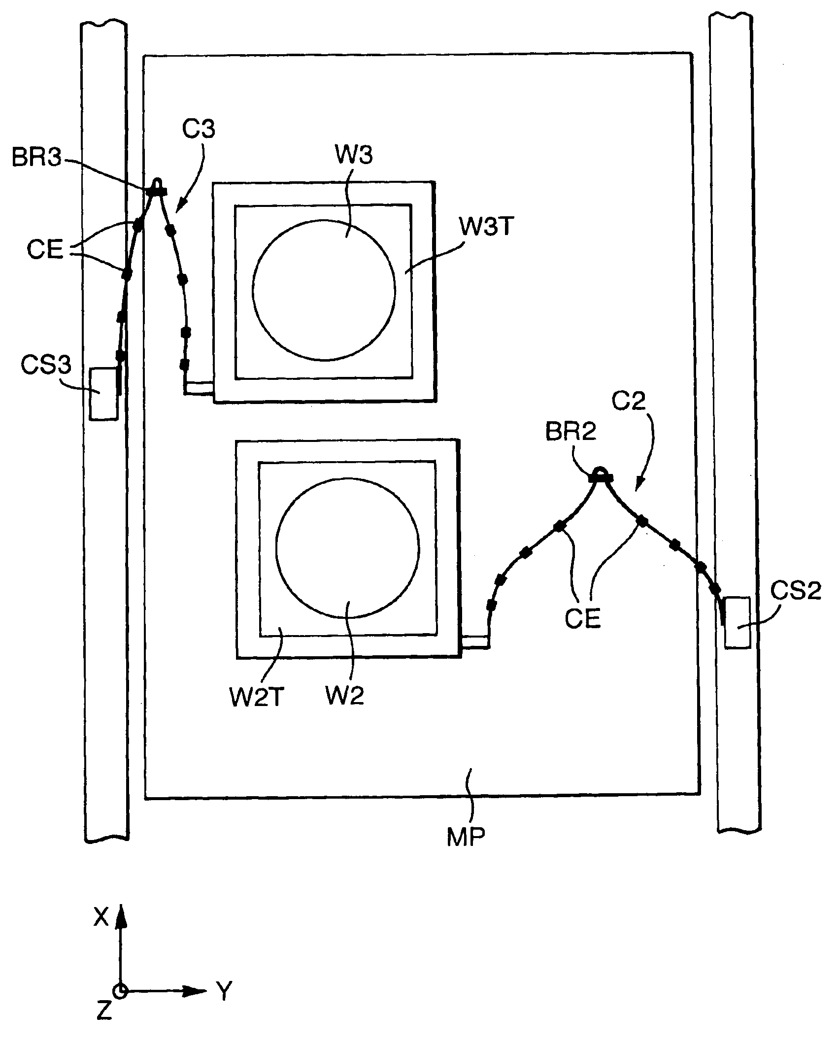
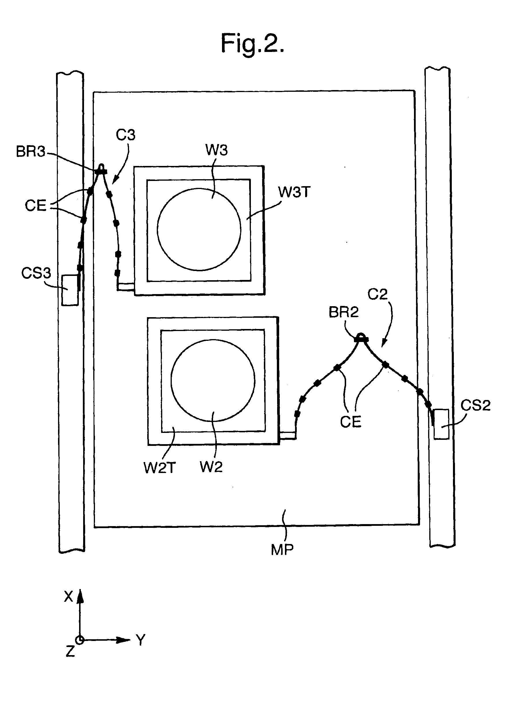
[0028]FIG. 2 is a schematic plan view showing a conduit for employing a flexible metal bellow according to an exemplary embodiment of the present invention;

[0029]FIG. 3 is a view in perspective on the conduit shown in FIG. 2;

[0030]FIG. 4 is a cross-sectional view on the flexible metal bellows according to the invention and for usage in the conduit in FIGS. 2 and 3, and

[0031]FIG. 5 is a schematic view on a conduit according to a second exemplary embodiment of the present invention.

[0032]In the Figures, corresponding reference symbols indicate corresponding parts.

DETAILED DESCRIPTION

[0033]FIG. 1 schematically depicts a lithographic projection apparatus 1 for including radiation system LA, IL constructed and arranged to supply a projection beam PB of radiation (e.g. UV or EUV radiation, electrons or ions); a first (mask) object table MT provided with a first object (mask) holder constructed and arranged to hold a mask MA (e.g...


PUM

PropertyMeasurementUnit
wavelengthaaaaaaaaaa
total pressureaaaaaaaaaa
vacuum pressureaaaaaaaaaa

Abstract

A lithographic projection apparatus includes a conduit that supplies utilities to a movable component in a vacuum chamber such as an object table, associated motor or sensor. The conduit comprises flexible metal bellows preventing out-gassing of the conduit due to the vacuum in the vacuum chamber while allowing movement of the movable component in at least a first degree of freedom.

Description

BACKGROUND OF THE INVENTION[0002]1. Field of the Invention[0003]The present invention relates to a lithographic projection apparatus.[0004]2. Description of the Related Art[0005]The term “patterning device” as here employed should be broadly interpreted as referring to device that can be used to endow an incoming radiation beam with a patterned cross-section, corresponding to a pattern that is to be created in a target portion of the substrate. The term “light valve” can also be used in this context. Generally, the pattern will correspond to a particular functional layer in a device being created in the target portion, such as an integrated circuit or other device (see below). An example of such a patterning device is a mask. The concept of a mask is well known in lithography, and it includes mask types such as binary, alternating phase-shift, and attenuated phase-shift, as well as various hybrid mask types. Placement of such a mask in the radiation beam causes selective transmissio...

Claims


Application Information

Patent Timeline
Patent Type & Authority Patents(United States)
IPC IPC(8): G03F7/20H01L21/027
CPCG03F7/70991H01L21/027
Inventor JACOBS, HERNESVOSTERS, PIETHOL, SVEN ANTOIN JOHANVAN DER SCHOOT, HARMEN KLAASVAN DIESEN, ROBERT JOHANNES PETRUSCALLAN, DAVID WILLIAM
Owner ASML NETHERLANDS BV
Why Eureka
Try Eureka