Switching method for bidirectional line switched ring and node apparatus used in the ring
a switching method and bidirectional line technology, applied in the field of switching methods for bidirectional line switched rings and node apparatuses used in rings, can solve problems such as inability to know, and achieve the effect of stabilizing aps information
- Summary
- Abstract
- Description
- Claims
- Application Information
AI Technical Summary
Benefits of technology
Problems solved by technology
Method used
Image
Examples
first embodiment
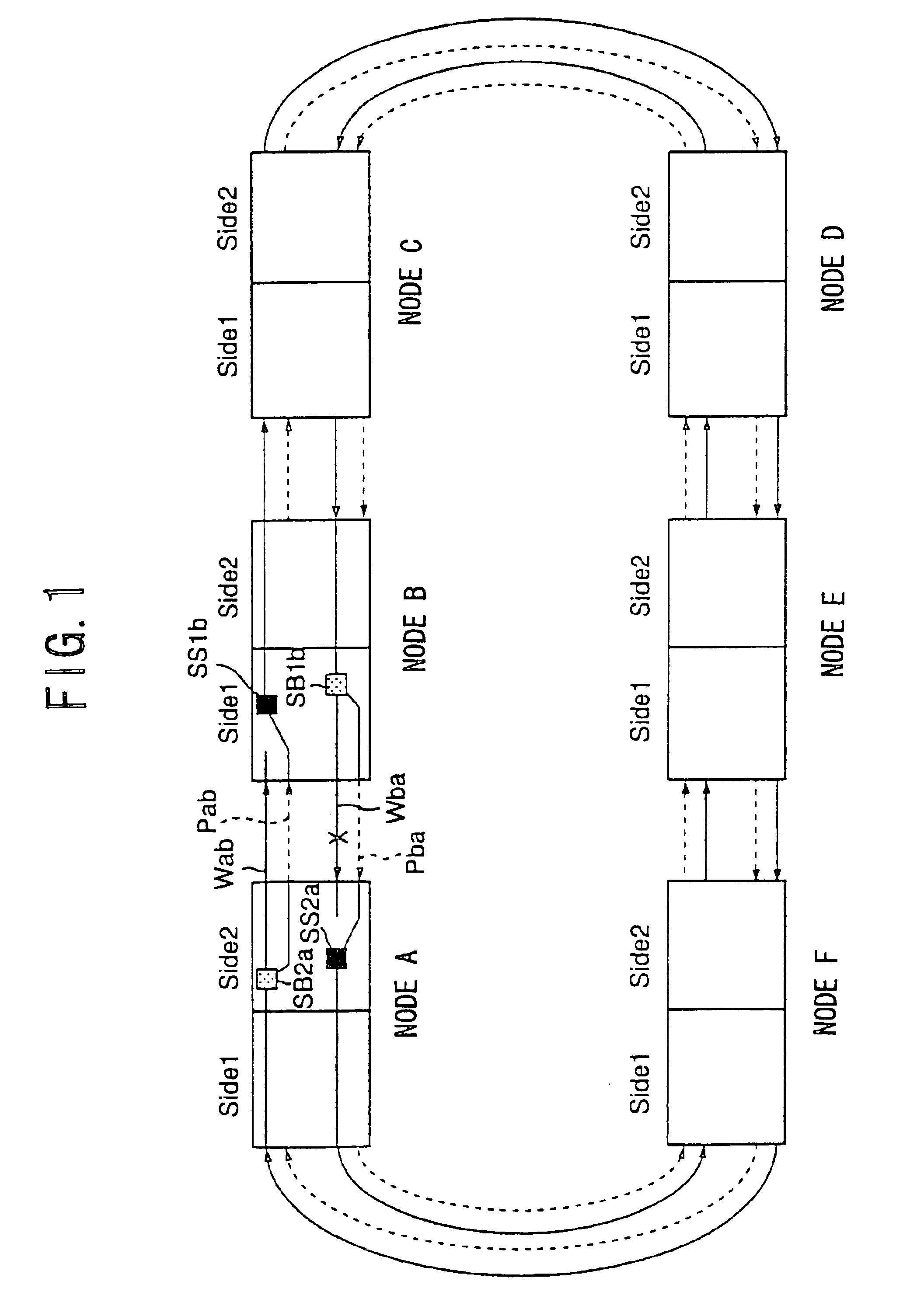
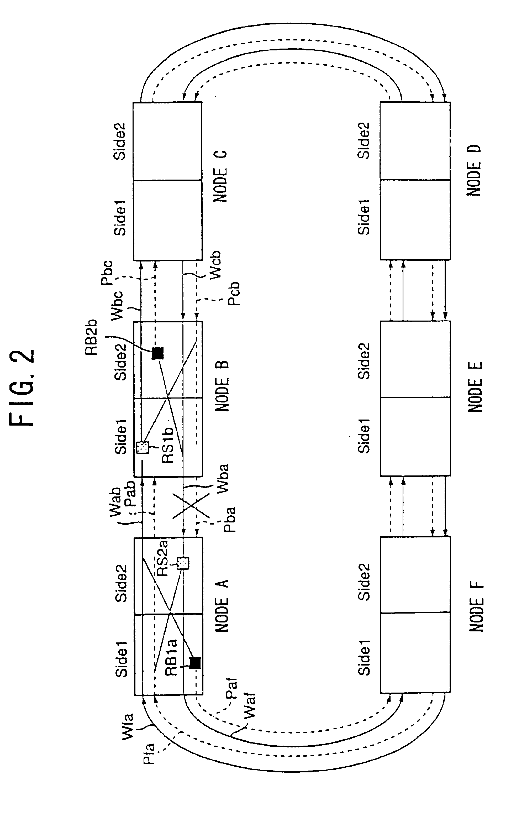
FIG. 5 shows an operation sequence in a first embodiment at a time a fault occurs between the nodes A and B according to the present invention. FIGS. 6A and 6B show lists of APS information at the time.
It is assumed that no fault exists in the ring as an initial condition. FIG. 6A shows the APS information at this time.
In FIGS. 6A and 6B, the first column indicates a symbol specifying APS information. K1 byte, first through fourth bits of the second column indicate switching request, but ‘NR’ represents ‘no request’. K1 byte, fifth through eighth bits of the third column indicate a transmission destination of the APS information. K2 byte, first through fourth bits of the fourth column indicate a transmission source of the APS information. K2 byte, fifth bit of the fifth column indicates short span by the value ‘0’ and long span by the value ‘1’. K2 byte, sixth through eighth bits of the sixth column indicate a status of the transmission source.
Then, it is assumed that a serious faul...
fourth embodiment
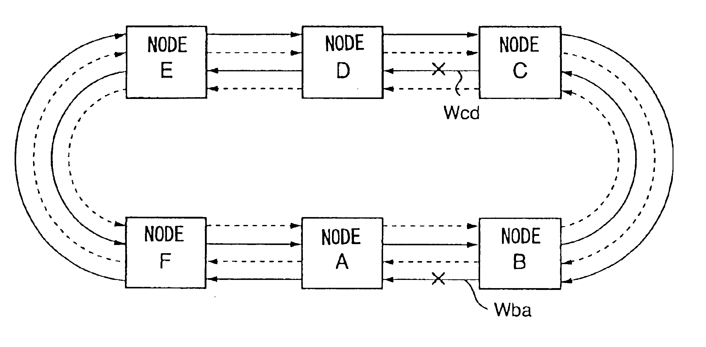
A case where, in the condition in which the serous fault exists between the nodes A and B in the working line Wba shown in FIG. 3, a serious fault occurs in the working line Waf and protection line Paf between the nodes A and F indicated by ‘X’ in FIG. 15 will now be described. FIG. 16 shows an; operation sequence in a fourth embodiment performed when a fault occur in the nodes A and F according to the present invention. FIG. 17 shows a list of APS information in this case.
The process from the time T5 to the time T7 in FIG. 16 is the same as the process from the time T5 to the time T6 in FIG. 12, and the list of APS information in this time is the same as those of FIGS. 6A and 6B.
When the time T7 is reached in FIG. 16, the node F detects a serious fault SF in the working line Waf and protection line Paf from the node A. Thereby, the node F performs ring switch (operates the ring bridge and ring switch), and transmits APS information f3 and f4 of ring switch (SF-R) shown in FIG. 17.
W...
fifth embodiment
FIG. 20 shows an operation sequence in a fifth embodiment performed when a fault occurs between the nodes A and F. FIG. 21 shows a list of APS information thereof.
At the time T8 in FIG. 20, the node A detects a serious fault SF in the working line Wba from the node B, performs span switch (SF-S), and transmits APS information a3 and a4 of span switch (SF-S) request shown in FIG. 6B to the adjacent nodes B and F. However, the node A receives APS information b2 of ‘NR’ shown in FIG. 6A, and does not receive response to reception of the span switch (SF-S) request.
Then, the time T9 is reached, the node F detects a serious fault SF in the working line Waf from the node A, performs span switch (SF-S), and transmits APS information f5 and f6 of span switch (SF-S) request shown in FIG. 21 to the adjacent nodes A and E.
When receiving the APS information f5, the node A performs span switch (operates the span bridge), and transmits APS information a13 of span switch (SF-S) request and APS info...
PUM
 Abstract
Description
Claims
Application Information
 - R&D
- Intellectual Property
- Life Sciences
- Materials
- Tech Scout
- Unparalleled Data Quality
- Higher Quality Content
- 60% Fewer Hallucinations
Browse by: Latest US Patents, China's latest patents, Technical Efficacy Thesaurus, Application Domain, Technology Topic, Popular Technical Reports.
© 2025 PatSnap. All rights reserved.Legal|Privacy policy|Modern Slavery Act Transparency Statement|Sitemap|About US| Contact US: help@patsnap.com


