Switching system and switching control method

a switching system and control method technology, applied in data switching networks, multiplex communication, digital transmission, etc., can solve the problems of traffic congestion and large size of the switching system, and achieve the effect of simple configuration and procedur

Inactive Publication Date: 2005-04-12
HITACHI LTD +1
View PDF24 Cites 13 Cited by
  • Summary
  • Abstract
  • Description
  • Claims
  • Application Information

AI Technical Summary

Benefits of technology

An object of the present invention is to integrate or interconnect the foregoing existing communication networks. More specifically, it is an object of the invention to provide a switching system, which is suitably used for configuring a communication network to realize integration or interconnections among the existing communication networks, and a control method thereof by a simple configuration and a procedure.
ATM switch can allocate all the resources to be used for ATM cell transfer (switching) among the function blocks except while communications are carried out temporarily by an in-channel of control signals. The ATM switch performs ATM cell transfer (self-routing) among the function blocks while preventing cell clashing. Accordingly, by providing a path between the function blocks for the ATM switch and using this path to select a function block for executing control to be performed in the switching system and then transferring information, each function block can pursue its own processing.

Problems solved by technology

In the case of configuring the foregoing switching system, a size of the switching system becomes large, and traffic congestion occurs as a result of efforts to obtain various services from the plural kinds of networks.

Method used


Image

  • Switching system and switching control method
  • Switching system and switching control method
  • Switching system and switching control method

Examples


Embodiment Construction

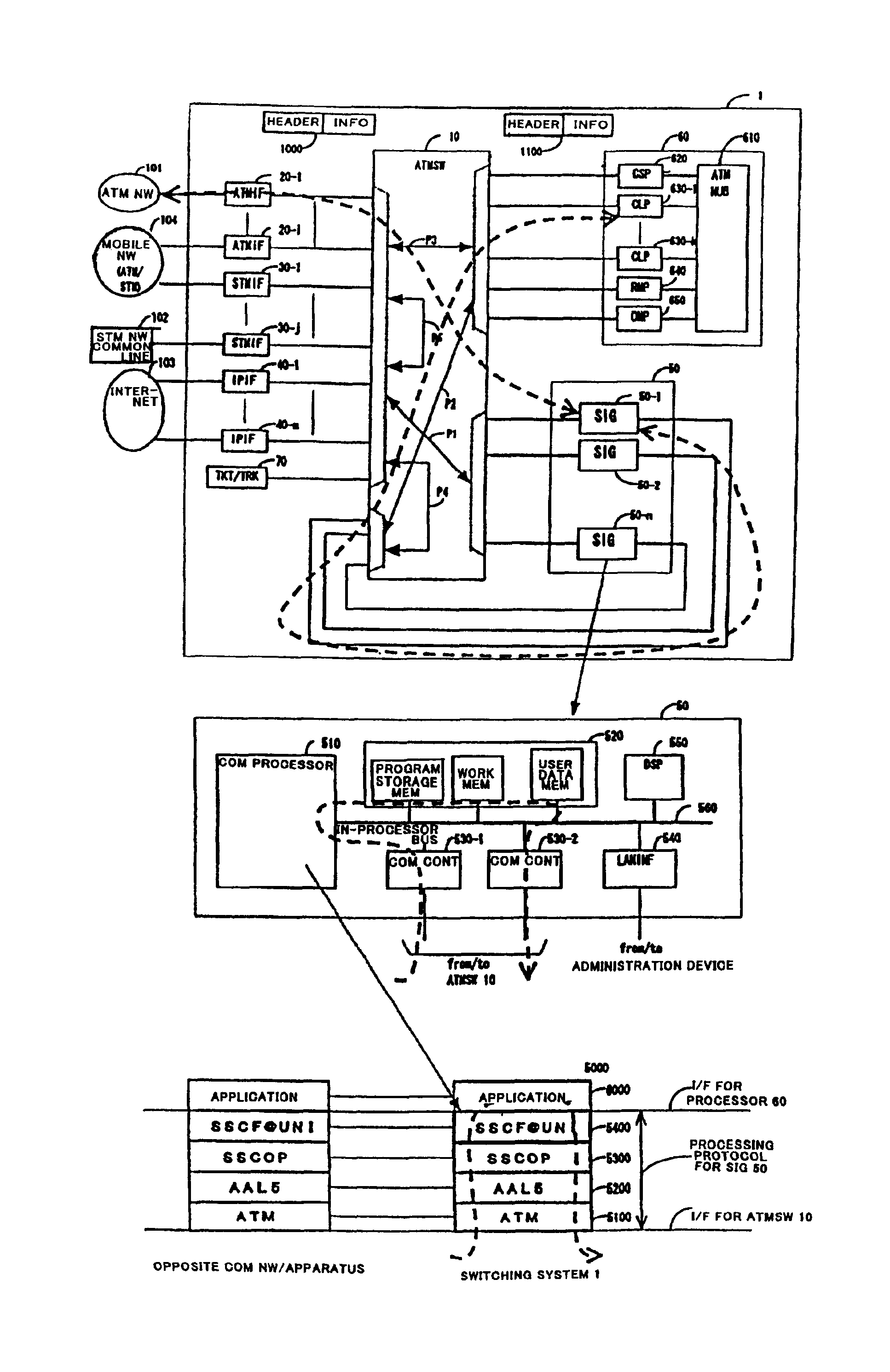
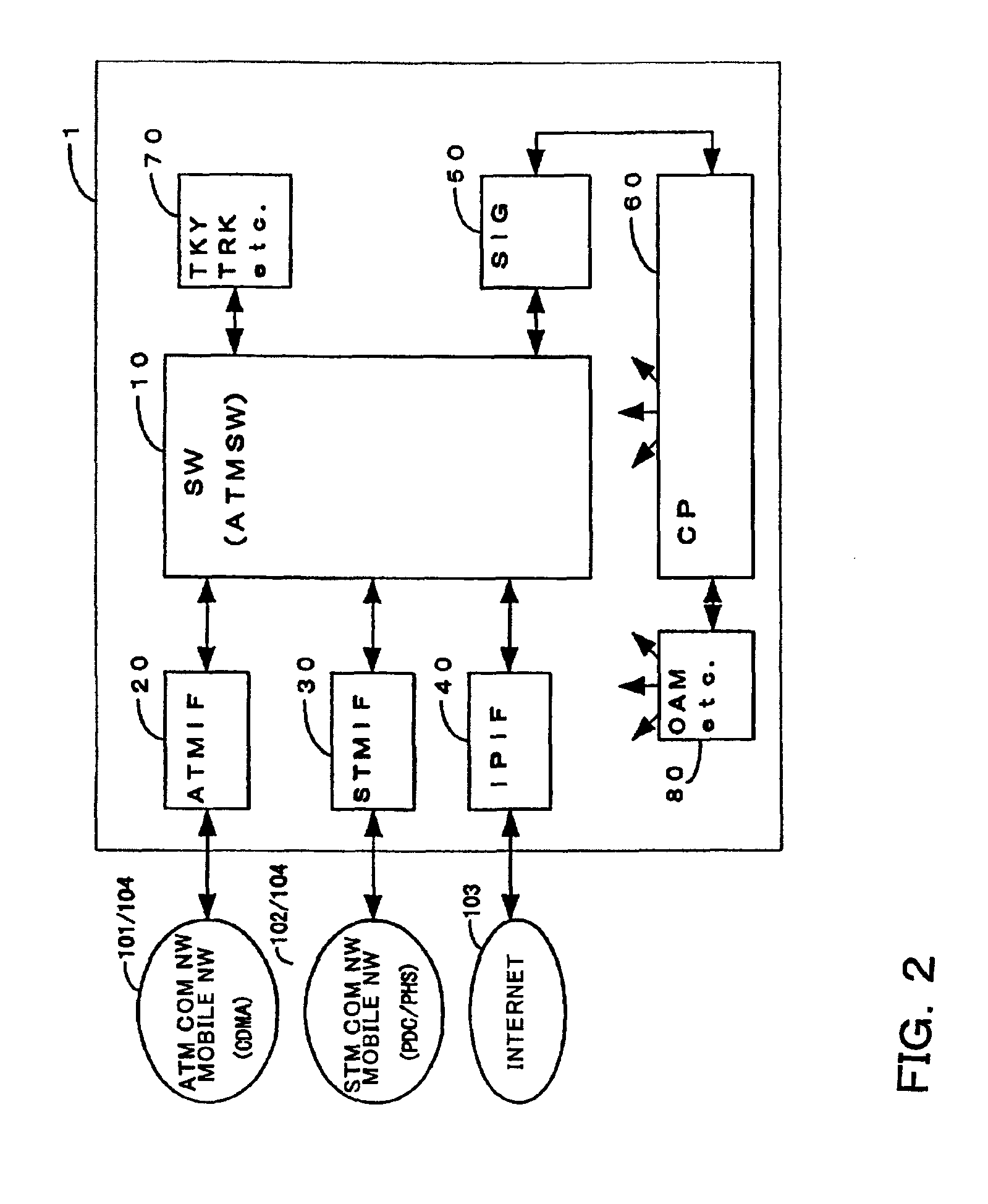
Next, description will be made of a switching system of the present invention, a configuration of a communication network employing this switching system, a switching control method and a mode of carrying out communication network control with reference to the accompanying drawings.

The embodiments of the invention described hereinbelow are only examples, and the switching system of the invention, the communication network employing the same and the switching control method can be applied to interconnections with communication networks of other kinds, such as a connection between an ATM communication network and an IP communication network, between an STM communication network and the IP communication network or the like.

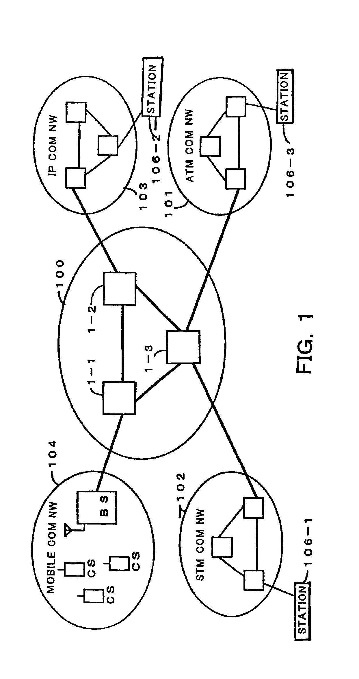
FIG. 1 is a network configuration view showing a configuration example of a communication network employing a switching system of the present invention. This communication network is configured in a manner that some networks are connected to a multimedia communicatio...


PUM


Abstract

A switching system for realizing integration of existing communication networks or interconnections thereof, and a switching control method. After a call is originated from an ATM communication network 101 to an STM communication network 102, an ATMIF 20 that has received a connection request signal (control signal) converts the control signal into a format of an ATM cell 1000, adds a header destined to one of SIG 50-1 to n for processing control signals, and then output the same. An ATMSW 10 performs self-routing based on header information. The selected one of the SIG 50-1 to n performs conversion for the ATM cell 1000 by a specified protocol, makes an ATM cell 1100 having a header destined to one of CLP 630-1 to k for processing control signals, and then output the same. Upon having received the ATM cell 1100, the CLP 630 links up with other processors to perform call connection control, functions having been dispersed among the other processors.

Description

BACKGROUND OF THE INVENTIONThe present invention relates to a configuration of a switching system and a switching control method. More particularly, the invention relates to a switching system, which is suitably used for processing plural kinds of media (voice / image / data) communicated by a variety of media at various speeds, and a control method thereof.In today's digital communication network, each medium of a voice, an image or data is communicated through a variety of communication networks. For example, these communication networks may include the following: (1) a packet communication network for performing communications by carrying signals on variable length packets, which is described in “Basic Knowledge on Data Exchange” issued by The Telecommunications Association (TTA); (2) a Synchronous Transfer Mode (STM) communication network for performing communications by carrying signals in time slots divided by time in a synchronized frame, which is described in “Easy Digital Switc...

Claims


Application Information

Patent Timeline
Patent Type & Authority Patents(United States)
IPC IPC(8): H04L12/56H04L12/64H04Q3/00H04L12/66H04L47/43
CPCH04L49/1507H04L49/256H04L49/1561H04L49/253
Inventor HIRAYAMA, KOJISHIBATA, HARUOKAWASE, AKIOIWAKI, SHINICHI
Owner HITACHI LTD
Why Eureka
Try Eureka