
Method and apparatus for efficient video processing

a video data and video processing technology, applied in the field of compression of video data, can solve the problems of reducing the overhead of video-intensive applications, reducing the bandwidth of current transmission modes, and consuming precious bitstream space, so as to reduce overhead, increase compression efficiency, and reduce the effect of overhead

Inactive Publication Date: 2005-04-12
ALTERA CORP
View PDF14 Cites 11 Cited by
  • Summary
  • Abstract
  • Description
  • Claims
  • Application Information

AI Technical Summary

Problems solved by technology

As consumers desire more video-intensive modes of communications, the limited bandwidth of current transmission modes (e.g., broadcast, cable, telephone lines, etc.) becomes prohibitive.
Further, video-intensive applications require immense storage capacity.
Most digital signals contain a substantial amount of redundant, superfluous information.
These methods are more appropriately termed still-image compression routines, as they work reasonably well on individual video image frames but do not attempt to address the issue of temporal, or frame-to-frame, redundancy, as explained in Section 2.2.
However, JPEG and similar compression schemes do not address the crucial issue of temporal redundancy.
Unfortunately, fractal compression is not a viable method of general compression.
In addition, fractal compression is very computationally intensive.
Although state of the art, block matching is highly inefficient and fails to take advantage of the known general physical characteristics or other information inherent in the images.
However, since blocks do not correspond to real objects, block-based systems cannot use this information to further reduce the bitstream.
Yet another major limitation of block-based matches arises because the residue created by block-based matching is generally noisy and patchy.
Thus, block-based residues do not lend themselves to good compression via standard image compression schemes such as DCT, wavelets, or fractals.
It is well recognized that the state of the art needs improvement, specifically in that the block-based method is extremely inefficient and does not produce an optimally compressed bitstream for motion video information.
While some compression gains are achieved, the associated overhead information is substantially increased because, in addition to the motion and residue information, these schemes require that structural or shape information for each object in a frame must also be sent to the receiver.
This is so because all current compression schemes use a dumb receiver—one which is incapable of making any determinations of the structure of the image by itself.

Method used


Image

  • Method and apparatus for efficient video processing
  • Method and apparatus for efficient video processing
  • Method and apparatus for efficient video processing

Examples


Embodiment Construction

1. Overview

The following sections provide a description of one embodiment of the invention using an encoder a decoder, and structural information (hereinafter in this embodiment “segments”) including details specific to this embodiment and not necessarily required in other embodiments of the invention.

1.1 Encoder

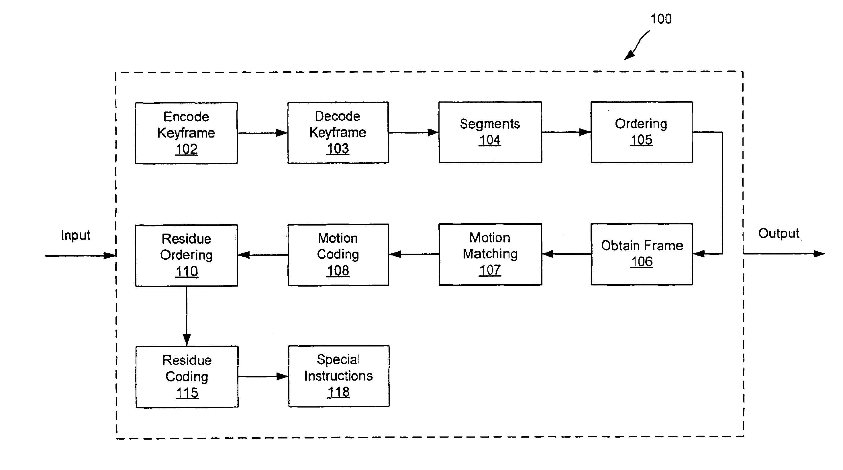
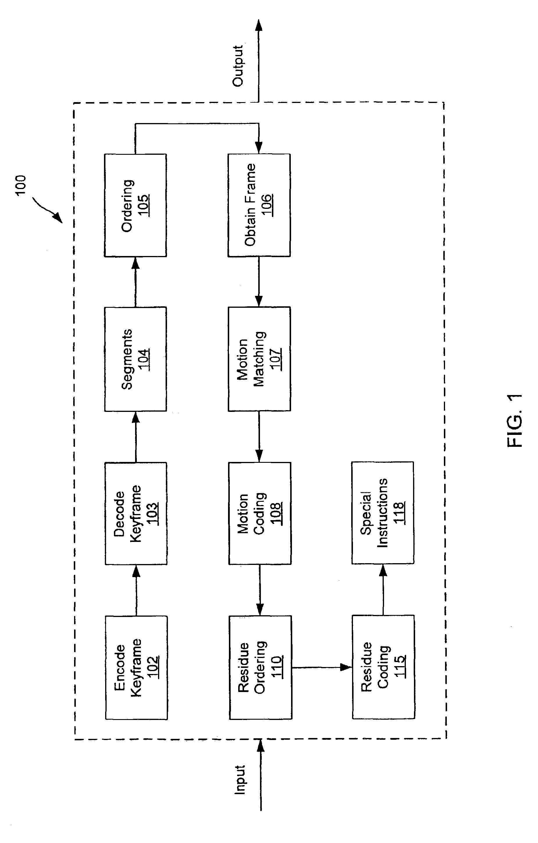
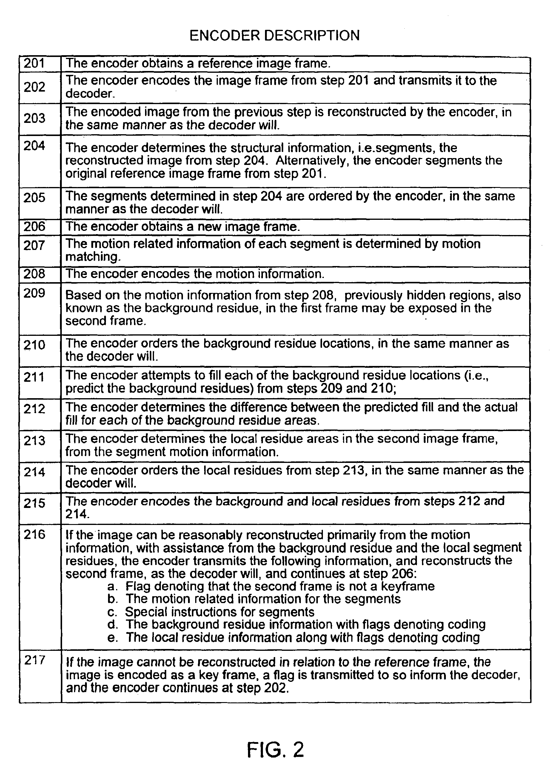
FIG. 1 is a block diagram of an exemplary encoder for use with a compatible decoder as will be described later with respect to FIG. 3 and FIG. 4, and FIG. 2 is an overview of the operation of the encoder of FIG. 1. At step 201, encoder 100 obtains a first (e.g., reference) image frame. At step 202, functional block 102 of encoder 100 encodes the image frame from step 201. At step 203, the encoded image from step 202 is reconstructed by functional block 103 of encoder 100, in the same manner as the decoder will reconstruct the image. At step 204, functional block 104 of encoder 100 segments i.e. obtains the structural information from, the reconstructed image, the segments be...


PUM


Abstract

A video compression method and apparatus uses an active decoder. The corresponding encoder can produce an encoded bitstream with a greatly reduced overhead by encoding a reference frame based on the structural information inherent to the image (e.g., image segmentation, geometry, color, and / or brightness), and then predicting other frames relative to the structural information. Typically, the description of a predicted frame would include kinetic information (e.g., segment motion data and / or associated residues representing information in previously occluded areas and / or inexact matches and appearance of new information, and portion of the segment evolution that is not captured by motion per se, etc.). Because the decoder is capable of independently determining the structural information (and relationships thereamong) underlying the predicted frame, such information need not be explicitly transmitted to the decoder. Rather, the encoder need only send information that the encoder knows the decoder cannot determine on its own.

Description

FIELD OF THE INVENTIONThe present invention relates generally to the compression of video data, and more particularly to a synchronized encoder and smart decoder system for the efficient transmittal and storage of motion video data.BACKGROUND OF THE INVENTION1. Brief IntroductionAs consumers desire more video-intensive modes of communications, the limited bandwidth of current transmission modes (e.g., broadcast, cable, telephone lines, etc.) becomes prohibitive. The introduction of the Internet, and the subsequent popularity of the world wide web, video conferencing, and digital & interactive television require more efficient ways of utilizing existing bandwidth. Further, video-intensive applications require immense storage capacity. The advent of multi-media capabilities on most computer systems have taxed traditional storage devices, such as hard drives, to the limit.Compression allows digital motion video to be represented efficiently and cheaply. The benefit of compression is th...

Claims


Application Information

Patent Timeline
Patent Type & Authority Patents(United States)
IPC IPC(8): H04N7/36H04N7/50H04N7/26H04N7/46H04N5/262
CPCH04N19/59H04N19/46H04N19/51H04N19/196H04N19/61H04N19/107H04N19/12H04N19/17H04N19/80H04N19/20H04N19/23H04N19/517H04N19/507H04N19/52G06T9/001
Inventor PRAKASH, ADITYOPRAKASH, ENIKO F.
Owner ALTERA CORP
Learn More