System and method for multiplexing and demultiplexing optical signals using diffraction gratings

a technology of optical signals and diffraction gratings, applied in the field of optical communication systems, can solve the problems of limiting the application of bdg devices to its gaussian-shape spectral response, significant loss of that frequency, and typically some frequency drift that will occur, so as to achieve the effect of substantially reducing the disadvantages and eliminating the problems of optical communication systems

Inactive Publication Date: 2005-04-12
EZCONN
View PDF20 Cites 7 Cited by
  • Summary
  • Abstract
  • Description
  • Claims
  • Application Information

AI Technical Summary

Benefits of technology

In accordance with the present invention, the disadvantages and problems associ...

Problems solved by technology

However, a drawback that limits the application of BDG devices is its Gaussian-shape spectral response.
As a result, any drift or offset of a frequency from its specified value (e.g., an ITU frequency) ...

Method used


Image

  • System and method for multiplexing and demultiplexing optical signals using diffraction gratings
  • System and method for multiplexing and demultiplexing optical signals using diffraction gratings
  • System and method for multiplexing and demultiplexing optical signals using diffraction gratings

Examples


Embodiment Construction

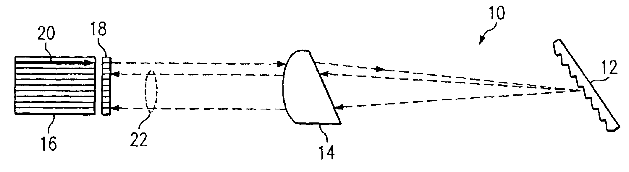
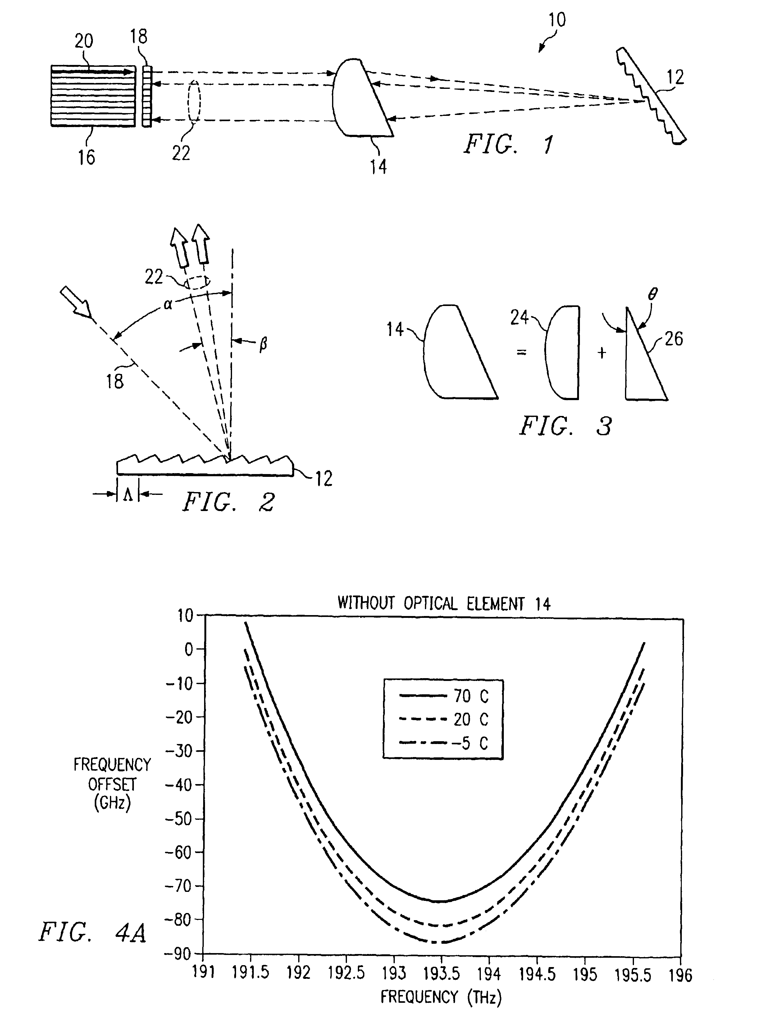
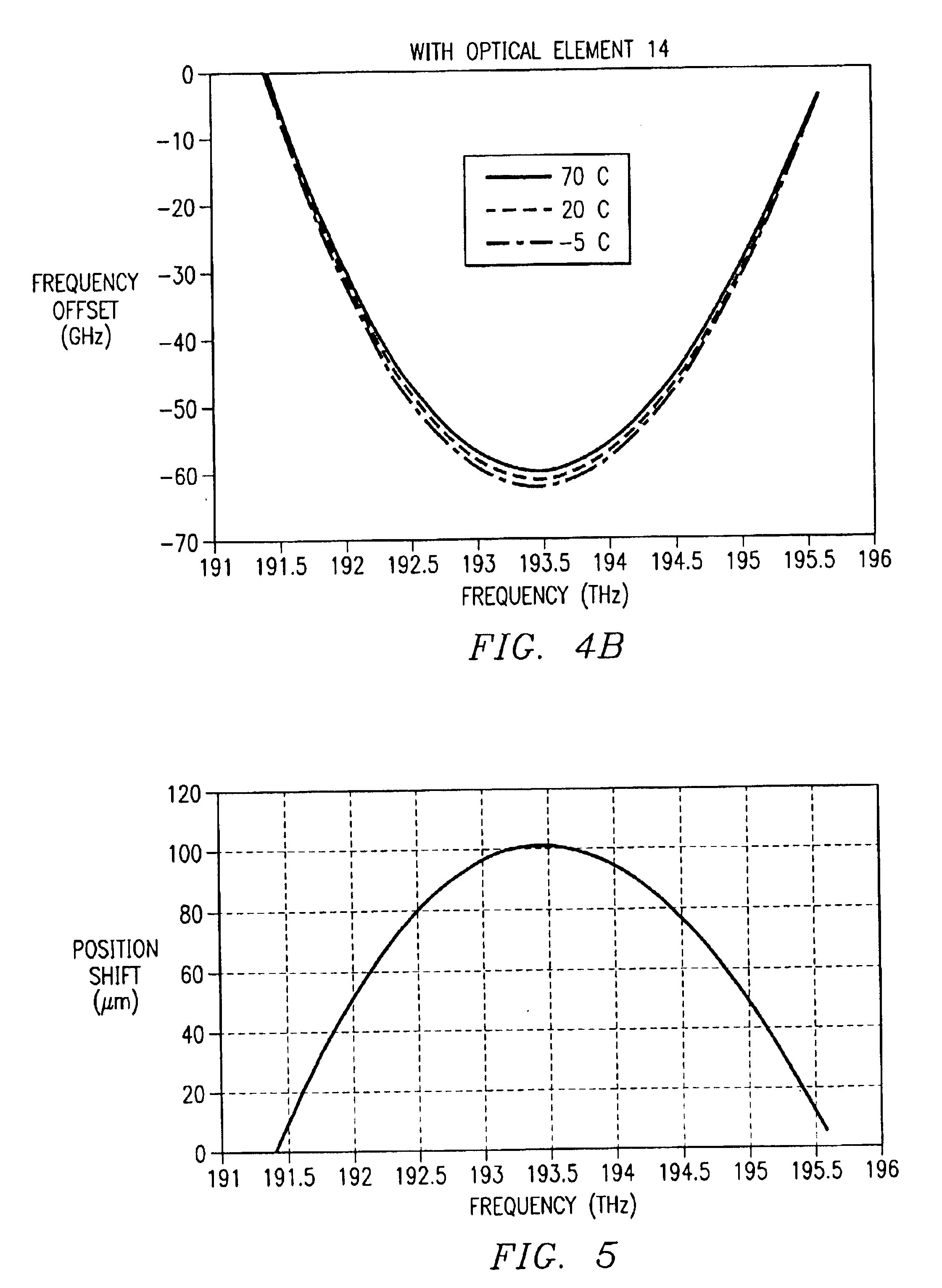
FIG. 1 illustrates one embodiment of an optical device 10 that includes a diffraction grating 12, a refractive optical element 14, and a fiber array 16. In some embodiments, device 10 further comprises a lens array 18. In general, device 10 performs a multiplexing function and / or a demultiplexing function upon an optical signal. When performing the multiplexing function, device 10 combines a plurality of spatially separated light beams, each light beam comprising a separate wavelength channel, into a single, more densely spaced wavelength division multiplexed (WDM) optical signal. The multiplexing function of device 10 is described in greater detail below. When performing the demultiplexing function, device 10 separates a WDM optical signal, such as optical signal 20, into a plurality of spatially separated light beams 22, each light beam comprising a separate wavelength channel. Device 10 compensates for temperature fluctuations and non-linear dispersion that may be introduced by t...


PUM


Abstract

An optical device for demultiplexing an optical signal comprises a grating that receives an optical signal comprising a plurality of wavelength channels, and generates a plurality of spatially separated light beams. Each light beam is associated with a particular wavelength channel. The optical device further comprises an optical element that at least partially compensates a temperature based frequency shift associated with the spatially separated light beams. The optical device further comprises a plurality of lenses and a plurality of fibers. The plurality of lenses are arranged such that a spacing between at least a pair of lenses is determined to at least partially compensate a non-linearity introduced by the grating. Each fiber is associated with a corresponding lens and receives a corresponding light beam. At least one fiber is placed a distance that is less than a focal length associated with its corresponding lens.

Description

TECHNICAL FIELD OF THE INVENTIONThe present invention relates generally to the field of optical communications systems. More specifically, the present invention relates to a system for multiplexing and demultiplexing optical signals using diffraction gratings.BACKGROUND OF THE INVENTIONBulk diffraction grating (BDG) based multiplexer / demultiplexer (Mux / Demux) devices have recently found application in dense wavelength division multiplexing (DWDM) optical communication systems. Compared to other techniques for processing DWDM optical signals (e.g., fiber Bragg grating, arrayed waveguide grating, thin film filters), BDG provides an economical way for high channel count DWDM solutions. However, a drawback that limits the application of BDG devices is its Gaussian-shape spectral response. As a result, any drift or offset of a frequency from its specified value (e.g., an ITU frequency) may result in significant loss of that frequency. Although the laser source can be controlled and the f...

Claims


Application Information

Patent Timeline
IPC IPC(8): G02B6/34
CPCG02B6/2713G02B6/2938G02B6/2931G02B6/2793
Inventor WONG, SENG-LEONGLIN, LEO YU-YULU, YANQING
Owner EZCONN
Why Eureka
Try Eureka