Guide wire insertion and re-insertion tools and methods of use

a technology of guide wires and catheters, applied in the field of endoscopic devices and methods of use, can solve the problems of time-consuming, tedious, and difficult tasks, and achieve the effect of convenient retraction

Inactive Publication Date: 2005-04-12
SCI MED LIFE SYST
View PDF147 Cites 93 Cited by
  • Summary
  • Abstract
  • Description
  • Claims
  • Application Information

AI Technical Summary

Benefits of technology

The present invention provides an insertion tool and method for easily inserting a guide wire into a catheter, particularly a rapid exchange catheter, for use in an endoscope. An insertion tool in accordance with an embodiment of the present invention includes a main body having a lumen sized to accommodate the catheter and a funnel-shaped extension having a funnel-shaped lumen that merges with the main lumen. The funnel-shaped lumen has a large first opening and a smaller second opening aligned with the guide wire lumen of the catheter such that, when the catheter is disposed in the main lumen, the guide wire may be easily inserted into the large opening of the funnel-shaped lumen and into the guide wire lumen of the catheter.
The present invention also provides a re-insertion tool and method for re-inserting a guide wire into a channel of a catheter. The re-insertion tool is particularly useful in combination with an endoscope and a SOE catheter disposed therein. Because the endoscope may be too small to accommodate the guide wire and the catheter side-by-side, it is desirable to reintroduce the guide wire into the channel of the catheter proximal of the port of the endoscope, before advancing or retracting the catheter and / or guide wire. Specifically, with the distal portion of the guide wire disposed in the channel / guide wire lumen of the catheter distal of the port of the endoscope, and the proximal portion of the guide wire disposed adjacent to the catheter proximal of the port, the re-insertion tool may be used to re-introduce the guide wire into the channel of the catheter proximal of the port. The re-insertion tool thereby facilitates easy retraction and advancement of the catheter and / or guide wire relative to the endoscope. Preferably, the reinsertion tool has an outside diameter greater than the inside diameter of the lumen of the endoscope. Also preferably, the lumen of the reinsertion tool has an inside diameter sized to accommodate the catheter, but less than the inside diameter of the lumen of the endoscope. The reinsertion tool may further include a keel sized to fit in the channel of the catheter.

Problems solved by technology

If the guide wire moves during such a procedure, the guide wire may have to be re-directed through the body ducts to the target site, which is often a difficult, time consuming, and tedious task.
This is difficult and often results in the movement of the guide wire and / or catheter.
Inserting a guide wire into the guide wire lumen of a rapid exchange catheter, whether in preparing the catheter and guide wire for insertion into the endoscope or performing a lo guide wire exchange procedure, is often difficult due to the relatively small size of the guide wire entry slot or port.
Specifically, the guide wire entry slot or port may be difficult to locate on the catheter shaft and, even after the guide wire slot or port has been located, inserting the guide wire into the guide wire lumen may be as difficult as threading a needle.

Method used


Image

  • Guide wire insertion and re-insertion tools and methods of use
  • Guide wire insertion and re-insertion tools and methods of use
  • Guide wire insertion and re-insertion tools and methods of use

Examples


first embodiment

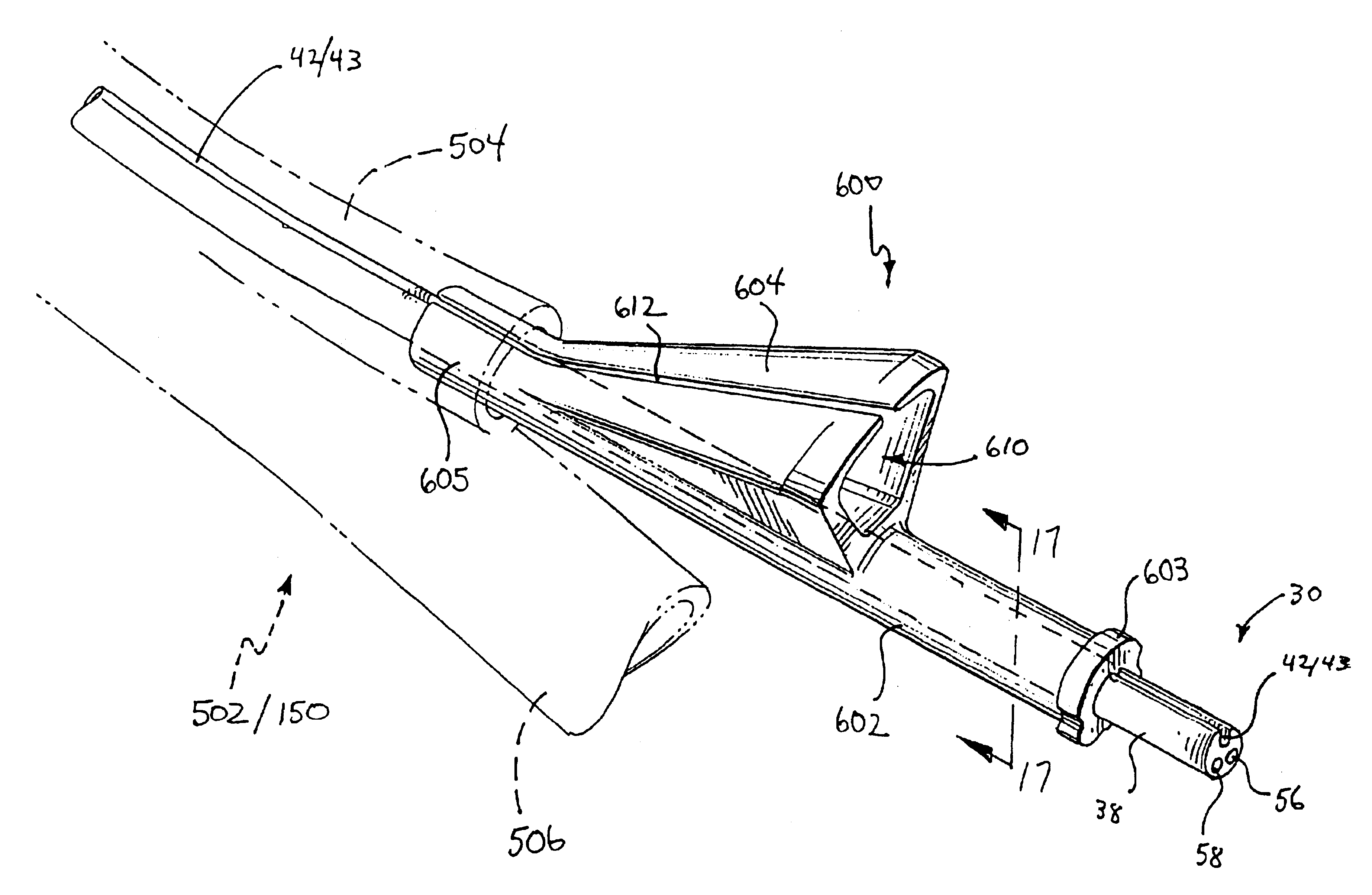
As illustrated in FIG. 17A, the main body 602 further includes a tongue or key 608 protruding from the interior wall of the main body 602 into the main lumen 606. The tongue or key 608 extends along at least a portion of the length of the main body 602 preferably from the proximal ridge portion 603 to a point proximal of the distal merged section 605. The tongue 608 is aligned with the slot 42 / 43 and is sized to slidingly fit within the slot 42 / 43. With this arrangement, the tongue 608 maintains proper rotational alignment between the insertion tool 600 and the catheter 30. Specifically, the tongue 608 maintains alignment between the distal opening of the funnel lumen 610 and the guide wire lumen 42 / 43 of the catheter 30 such that the guide wire is automatically aligned with the guide wire lumen 42 / 43 upon insertion into the proximal opening of the funnel lumen 610.

second embodiment

As illustrated in FIG. 17B, the main body 602 further includes a non-round engaging surface 614 extending along the interior wall of the main body 602 into the main lumen 606. The non-round engaging surface 614 extends along at least a portion of the length of the main body 602, preferably from the proximal ridge portion 603 to a point proximal of the distal merged section 605. The non-round engaging surface 614 is aligned with a similarly shaped surface 616 extending along the side of the catheter 30. Both the engaging surface 614 of the insertion tool 600 and the engaging surface 616 of the catheter 30 are non-round (e.g., flat) to inhibit the rotation of the catheter 30 relative to the insertion tool 600. Thus, the engaging surfaces 614 and 616 maintain alignment between the distal opening of the funnel lumen 610 and the guide wire lumen 42 / 43 of the catheter 30 such that the guide wire is automatically aligned with the guide wire lumen 42 / 43 upon insertion into the proximal open...


PUM


Abstract

An insertion tool and method for easily inserting a guide wire into a guide wire lumen of a catheter, particularly a rapid exchange catheter, for use in an endoscope. The insertion tool includes a main body having a main lumen and a funnel-shaped extension having a funnel lumen that merges with the main lumen. The funnel lumen has a first large opening and a second smaller opening aligned with the guide wire lumen of the catheter such that, when the catheter is disposed in the main lumen, the guide wire may be easily inserted into the large opening of the funnel-shaped extension and into the guide wire lumen of the catheter. Also, a re-insertion tool and method for re-inserting a guide wire into a channel of a catheter. The re-insertion tool is particularly useful in combination with an endoscope and an SOE catheter disposed therein.

Description

FIELD OF THE INVENTIONThe present invention generally relates to endoscopic devices and methods of use. Specifically, the present invention relates to catheters for use in combination with guide wires and endoscopes.BACKGROUND OF THE INVENTIONEndoscopic procedures for treating abnormal pathologies within the alimentary canal system and biliary tree (including the biliary, hepatic, and pancreatic ducts) are increasing in number. The endoscope provides access to the general area of a desired duct using direct visualization. However, the duct itself must be navigated using a catheter in conjunction with fluoroscopy and guide wires.Catheters are known for treatment of targeted anatomical regions. Known methods and devices for using biliary catheters for accessing the biliary tree for performing catheter procedures are disclosed in Weaver et al., U.S. Pat. No. 5,397,302 and Karpiel, U.S. Pat. No. 5,320,602, the disclosures of which are herein incorporated by reference. In general, for tr...

Claims


Application Information

Patent Timeline
Patent Type & Authority Patents(United States)
IPC IPC(8): A61M25/01A61M25/00A61M29/02A61MA61B1/00A61M25/09
CPCA61M25/0097A61M25/0169A61M25/0172A61M25/09041A61M25/02A61M2025/09125A61M2025/0183
Inventor WINDHEUSER, JAMES E.YEARICK, JAMESCARRILLO, JR., OSCARALLMAN, ROBERT C.ALVAREZ DE TOLEDO, FERNANDOEVANS, STEPHEN C.MAY, NORMAN C.
Owner SCI MED LIFE SYST
Why Eureka
Try Eureka