Computer system with storage system having re-configurable logical volumes

a computer system and storage system technology, applied in the direction of micro-instruction address formation, memory address/allocation/relocation, instruments, etc., can solve the problem that the area of each logical volume cannot be expanded during the operation of the system, and achieve the effect of facilitating the management of the logical volum

Inactive Publication Date: 2005-04-12
HITACHI LTD
View PDF3 Cites 31 Cited by
  • Summary
  • Abstract
  • Description
  • Claims
  • Application Information

AI Technical Summary

Benefits of technology

It is an object of the invention to enable the construction of a logical volume to be freely changed during operation of the system, for example, to expand a logical volume area in a storage. Specifically, an object of the invention is to provide a method of enabling the logical volume area to be expanded without releasing an existing logical volume area and expanding the logical volume area without interrupting an access to an existing logical volume.
According to the invention, the storage has logical volume control means for controlling the construction of the logical volume, and the logical volume control means is provided with a logical volume number map in which logical volume construction information is described. By describing the constructions of the computer and logical volumes and the combination with logical volumes in the storage which can be used by the computer, a construction change in the logical volumes can be freely made. By copying a plurality of separate logical volumes into a physically continuous area so as to be integrated to a single logical volume, management of the logical volume is facilitated.

Problems solved by technology

On the other hand, since the logical volumes are constructed in an inner continuous area, the area of each logical volume cannot be expanded during operation of the system without newly adding a physical disk.

Method used


Image

  • Computer system with storage system having re-configurable logical volumes
  • Computer system with storage system having re-configurable logical volumes
  • Computer system with storage system having re-configurable logical volumes

Examples


embodiment i

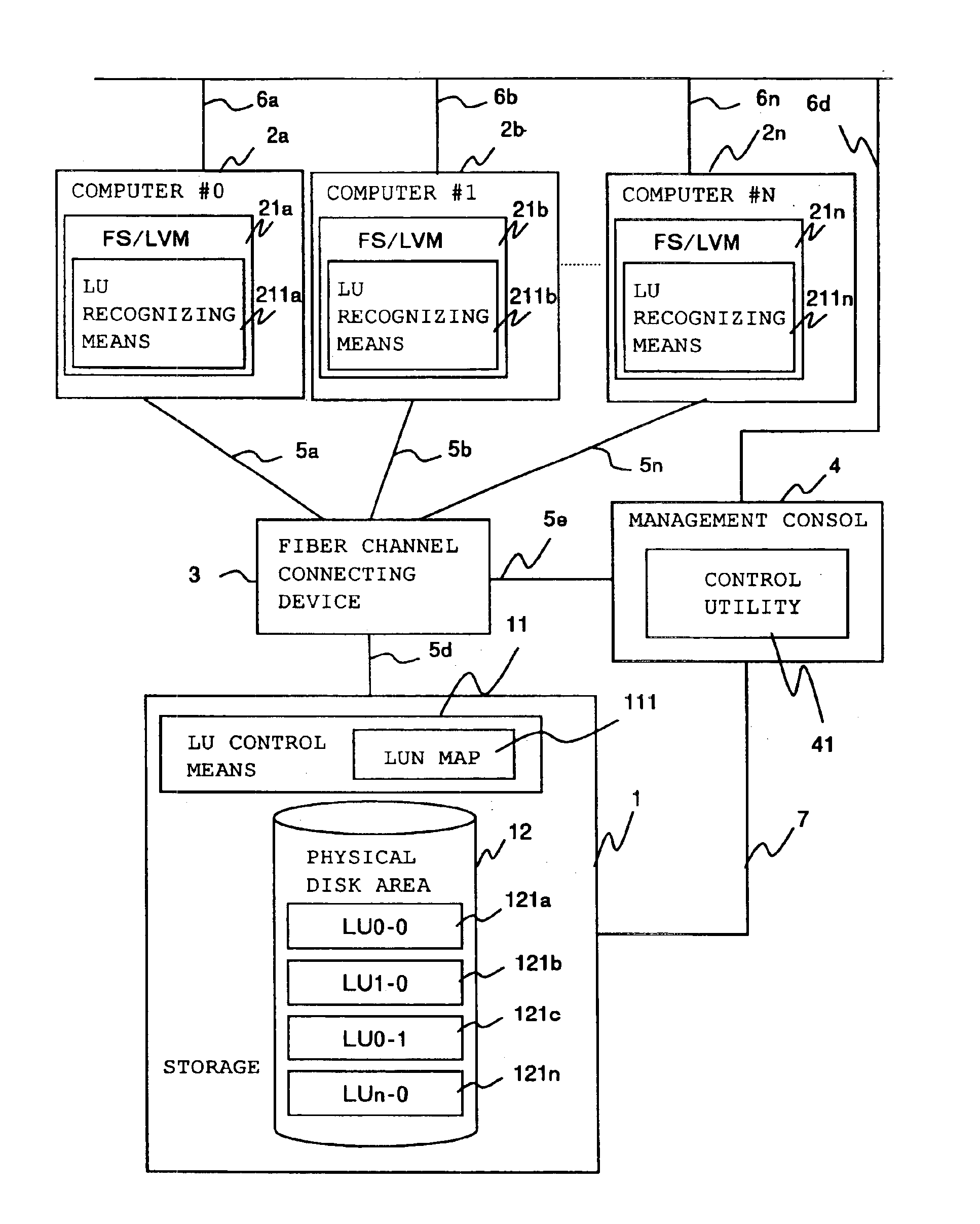
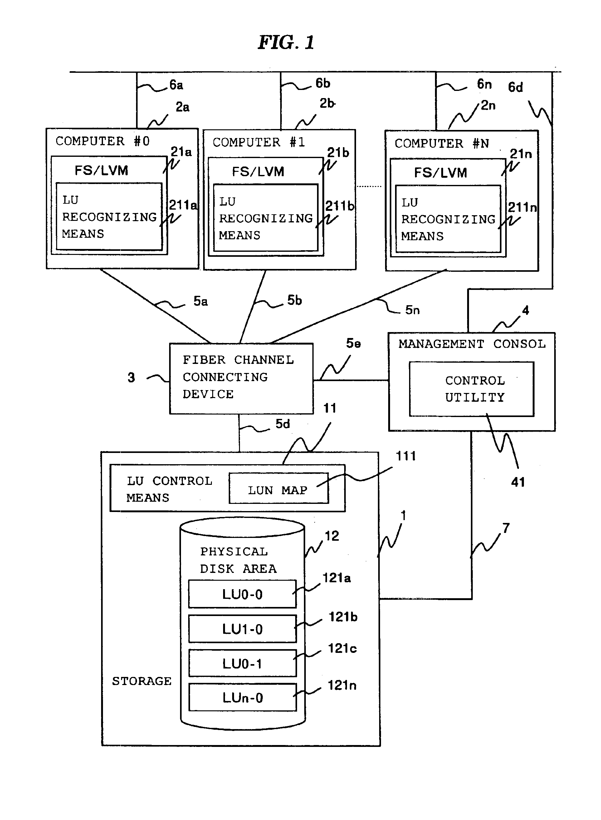
FIG. 1 is a diagram showing the configuration of a computer system according to a first embodiment. Shown in the diagram are computers 2x (2a, 2b, . . . , 2n), a storage 1 shared by all the computers 2x, a management console 4 for managing the computer system, a fiber channel connecting device 3 for connecting all the computers 2x, storage 1, and management console 4 with each other, fiber channels 5x (5a, 5b, . . . , 5n), a LAN (Local Area Network) 6x (6a, 6b, . . . , 6n) used for communications between the plurality of computers 2x and the management console 4, and communication means 7 used for communications between the storage 1 and the management console 4.

Each of the computers 2x has therein logical volume management software 21x (21a, 21b, . . . , 21n) called a file system FS or generally LVM, and a logical unit recognizing means 211x (211a, 211b, . . . , 211n) for recognizing a logical volume construction or the like of the storage 1 and notifying the logical volume managem...

embodiment ii

FIG. 8 is a diagram showing the configuration of a computer system according to a second embodiment. The construction of the computer system is the same as that of the first embodiment except for the point that a copy means 13 is added to the storage 1. The copy means 13 is a means for copying an LU to another area.

An LU construction change will be described by using the flowchart of FIG. 9. The operator of the management console 4 sends an indication for LU construction change from the control utility 41. In the case of expanding an LU, the inner LUN of the LU to be expanded and an expansion size are designated. This indication is sent to the storage 1 via the communication means 7 (step 801).

The LU control means 11 in the storage 1 receives the indication and determines whether the total size of the size of the designated inner LU and the expansion size can be assured from the free area or not (step 802).

When the area cannot be assured, the LU control means 11 sends an error signa...

embodiment iii

A third embodiment will be described. A computer system of the third embodiment is the same as that in the second embodiment. The third embodiment is realized by a combination of virtual combining of logical volumes in the first embodiment and expansion by the copying means in the second embodiment.

The LU construction change will be described by referring to the flowchart of FIG. 13.

The operator of the management console 4 sends an indication for LU construction change from the control utility 41. In the case of expanding the LU, all the inner LUNs assigned to the outer LU to be expanded and an expansion size are designated. The instruction is sent via the communication means 7 to the storage 1 (step 901).

The LU control means 11 in the storage 1 receives the instruction and determines whether the total size of the size of all the designated inner LUs and the expansion size can be assured in the free area or not (step 902).

If the area can be assured, all the designated LUs are copied...


PUM


Abstract

In order to enable an area of each logical volume to be expanded while continuously using the logical volume and to integrate separate logical volumes in a single continuous area, a storage has logical volume control means for controlling the construction of a logical volume, a logical volume number map in which logical volume construction information is described, and copy means for copying the logical volume. By allowing two or more inner logical numbers to be described per external logical number in the logical volume number map, improved flexibility in combining the logical volumes in the storage is achieved. By copying a plurality of separate logical volumes into a physical continuous area by the copy means, the logical volumes are integrated.

Description

BACKGROUND OF THE INVENTIONThe present invention relates to a method of changing the construction of a logical volume area in a storage and, more particularly, a method of expanding a logical volume area.Conventionally, as a method of expanding the capacity in a storage, an expansion method by adding a physical disk is known. The method will be described with reference to FIG. 15. Reference numeral 100 denotes a storage and 101 indicates a physical disk area as a collection of physical disks. In the physical disk area 101, logical volumes called LU (Logical Units) designated by reference numerals 1011x (1011a, 1011b, . . . ) are constructed. In the case of expanding the capacity of the storage, by adding a physical disk to the storage 100, as shown by a broken line, an added disk area 102 is generated. When the logical volumes LU1 (1011a) and LU2 (1011b) in the physical disk area 101 become full, a new logical volume LU3 (1011c) can be generated in the added disk area 102.However, i...

Claims


Application Information

Patent Timeline
Patent Type & Authority Patents(United States)
IPC IPC(8): G06F12/00G06F3/06G06F12/08
CPCG06F3/0608G06F11/1096G06F3/0689G06F3/0644
Inventor MIZUNO, YOICHIMATSUNAMI, NAOTOMURAOKA, KENJIMIMATSU, YASUYUKI
Owner HITACHI LTD
Why Eureka
Try Eureka