Check patentability & draft patents in minutes with Patsnap Eureka AI!

System and method for communicating device information between a device and a controller

Inactive Publication Date: 2005-04-12
INTEL CORP
View PDF13 Cites 18 Cited by
  • Summary
  • Abstract
  • Description
  • Claims
  • Application Information

AI Technical Summary

Problems solved by technology

This, combined with the fact that typical voltage requirements of chips is steadily decreasing with the reduction of chip size, causes there to be difficulty choosing the appropriate voltages to be represented by the 32-value range such that the range has both sufficient variance and sufficiently fine granularity.
Although this system provides for transmission of management information, it has many critical deficiencies, as explained below, limiting its ability to regulate a microprocessor's voltage.

Method used


Image

  • System and method for communicating device information between a device and a controller
  • System and method for communicating device information between a device and a controller
  • System and method for communicating device information between a device and a controller

Examples


Embodiment Construction

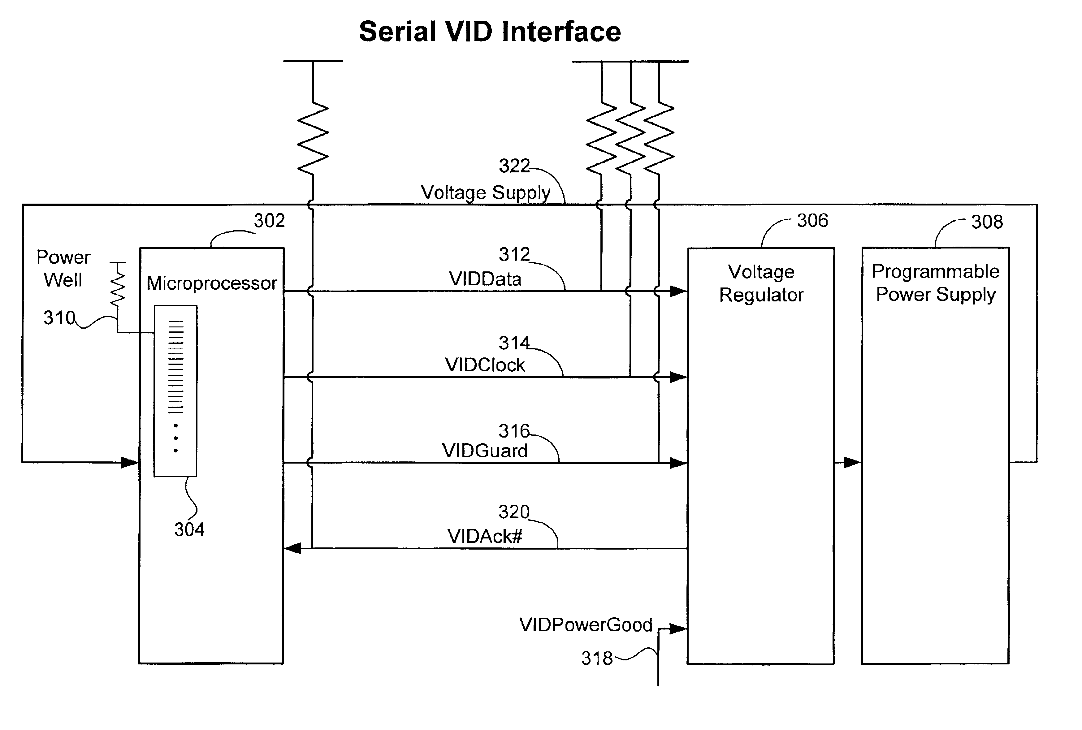
FIG. 3 provides a diagram illustrative of a serial VID interface under principles of the present invention. In one embodiment, having initial configuration coding for the microprocessor (chip) 302 incorporated into the combination of (pulsed and unpulsed) chip fuses 304, the voltage identifier (VID) is extracted for communication to a voltage regulator (VR) 306. Upon system power-up, voltage levels are unstable and / or erratic. In one embodiment, the VR 306 and the chip 302 have defined roles in sequencing the power supply 308. First, the VR 306 brings up an auxiliary power supply to power the chip's 302 power well 310. When the chip 302 has detected a valid power level at the power well 310, the chip 302 reads the intended VID from the chip fuses 304 and communicates the VID to the VR 306. At this point, in one embodiment, the VR 306 has started an RC timer (VIDPowerGood 318). When VIDPowerGood 318 tells the VR 306 that enough time has elapsed (and therefore, that the auxiliary powe...


PUM


Abstract

Embodiments of the present invention describe a system and method for microprocessor power regulation. An appropriate amount of voltage is provided to a microprocessor based on a voltage identifier (VID) received by a voltage controller from the microprocessor via a serial communication line. A voltage identifier clock signal (VIDClock) is used for the timing of transmission and receipt of data / acknowledgement signals. A guard clock signal (VIDGuard) is provided via a separate guard clock line to prevent potential noise on the clock line from causing a clock signal misidentification, which could cause a wrong value to be received as the VID. VIDGuard is analyzed in relation to ViDClock to verify the value of the clock signal. To verify receipt of the VID data, a voltage identifier acknowledgement line (VIDAck) is transmitted from the voltage regulator to the microprocessor. The acknowledgement signal is checked by a two-part receipt verification, high-to-low and low-to-high.

Description

BACKGROUND INFORMATIONThe present invention relates to microprocessor (chip) power regulation. More specifically, the present invention relates to a system and method for providing an appropriate amount of voltage to a microprocessor based on information received by a voltage controller from said microprocessor.Typical personal computers utilize a power supply to distribute a base potential of, for example, five volts (direct current, DC) to the various components of the system. In a continuing effort to minimize power consumption as well as heat production, developers strive to minimize chip voltage requirements. In order to convert the initial five-volt supply to an appropriate value for the chip, voltage regulation of some kind is required.A typical chip requirement has been 3.5 volts. In order to supply the correct amount of voltage to the chip, the manufacturer (or whomever may be the installer), reads a label on the chip providing voltage identification (VID) and, depending on...

Claims


Application Information

Patent Timeline
IPC IPC(8): G06F1/26
CPCG06F1/263
Inventor GREINER, ROBERT J.MA, MATTHEWOSBURN, EDWARD P.STAPLETON, MICHAEL
Owner INTEL CORP
Features
  • R&D
  • Intellectual Property
  • Life Sciences
  • Materials
  • Tech Scout
  • Unparalleled Data Quality
  • Higher Quality Content
  • 60% Fewer Hallucinations
Learn More