Rack-mounted equipment cooling

a rack-mounted equipment and cooling technology, applied in the direction of cooling fluid circulation, domestic cooling apparatus, lighting and heating apparatus, etc., can solve the problems of unsatisfactory heat, performance and reliability, affecting the useful life of components, etc., to improve the cooling efficiency of rack-mounted components, reduce hot spots, and increase the reliability of rack-mounted components

Inactive Publication Date: 2005-04-19
SCHNEIDER ELECTRIC IT CORP
View PDF11 Cites 110 Cited by
  • Summary
  • Abstract
  • Description
  • Claims
  • Application Information

AI Technical Summary

Benefits of technology

[0011]Various aspects of the invention may provide one or more of the following advantages. Higher volumes of colder air can be delivered to rack-mounted components than in other solutions. Reliability of rack-mounted components, e.g., servers, can be increased and hot spots reduced compared to previous designs. More components can be loaded into a rack without loss of reliability. Existing racks can be retrofitted to provide better cooling of rack-mounted components. A compact, high throughput, modular apparatus with few moving parts can be provided to new or existing racks to cool rack-mounted components. Electrical and mechanical failures of a rack-cooling apparatus are guarded against, e.g., with electrical and mechanical redundancy. Cooled air, and / or cooler-than ambient air, can be provided directly to rack-mounted equipment. The invention reduces / minimizes mixing of conditioned air with ambient air and may provide filtration. Variable amounts of cooling may be provided in response to variations of temperature and power consumption of rack-mounted components.

Problems solved by technology

Heat is undesirable as it affects performance and reliability of the rack-mounted components, e.g., including causing complete failures, and affects the useful life of the components.
Often, the heat produced by the rack-mounted components is not evenly distributed in the rack.
Unevenly distributed loads in the rack result in uneven heat production, or “hot spots.”

Method used


Image

  • Rack-mounted equipment cooling
  • Rack-mounted equipment cooling
  • Rack-mounted equipment cooling

Examples


Embodiment Construction

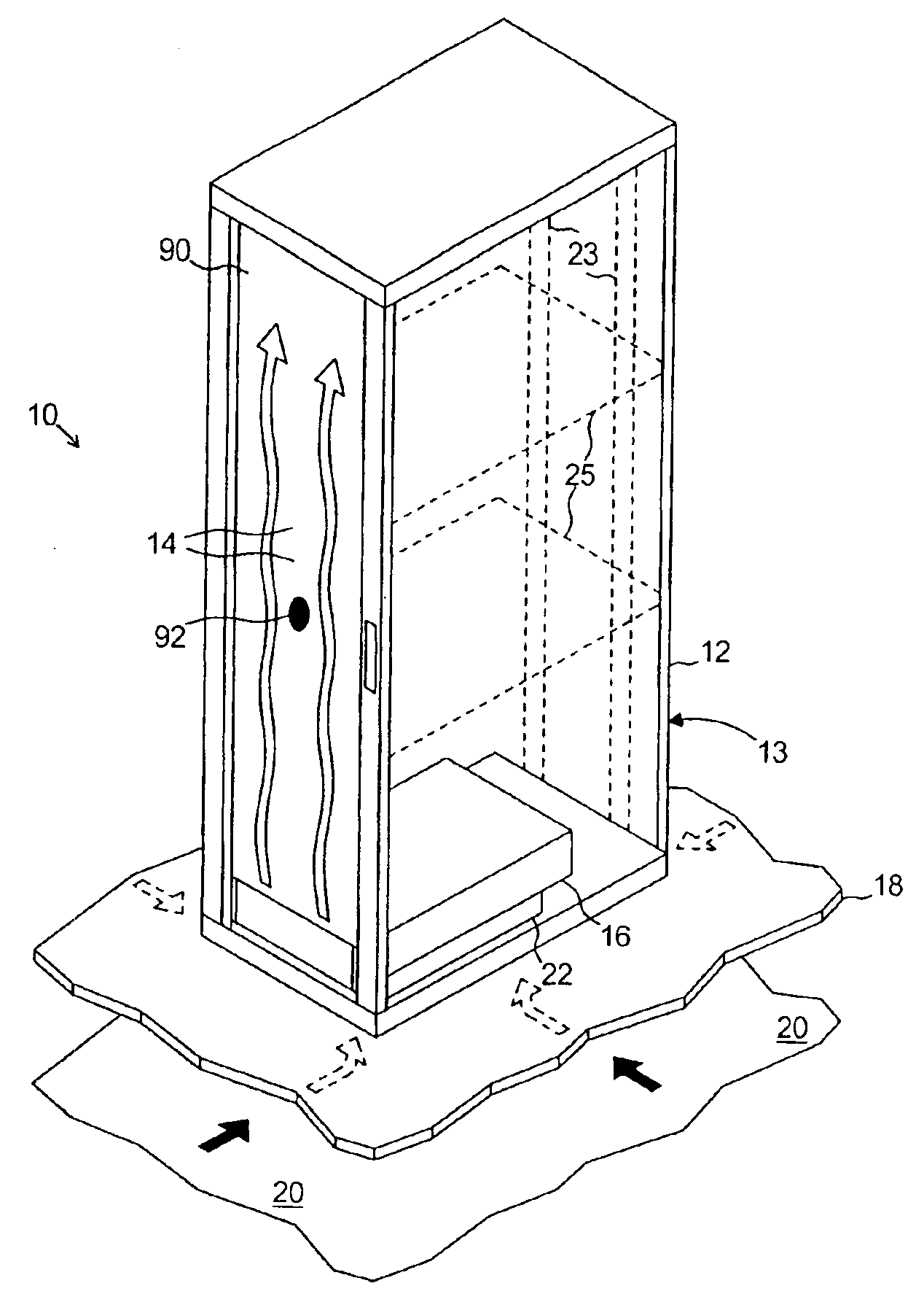
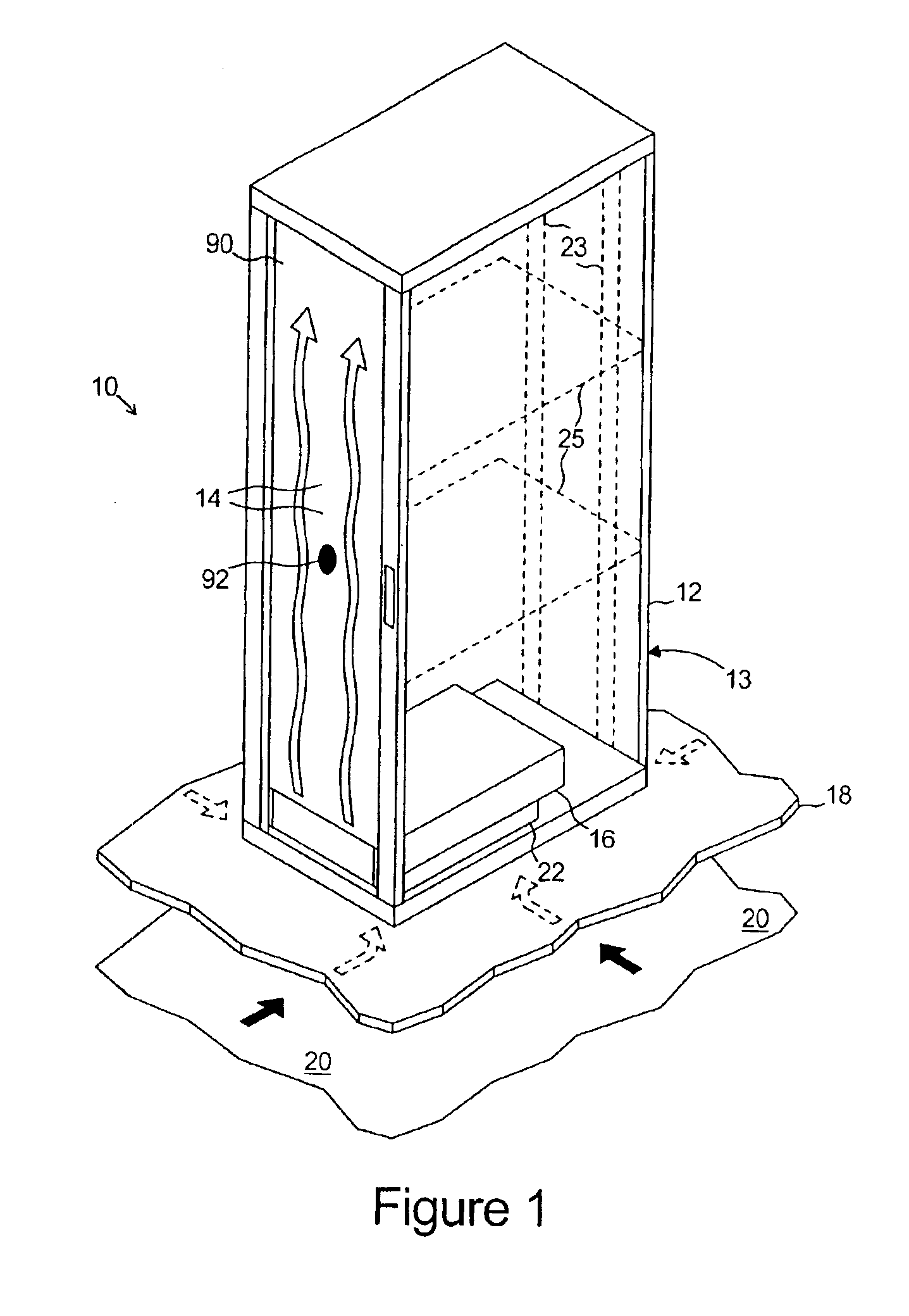
[0018]At least some embodiments of the invention provide techniques for cooling rack-mounted equipment. Embodiments of the invention include a modular, self-contained unit for cooling rack-mounted equipment where the unit has multiple fans for drawing air in through at least one input port and forcing the air out at least one exhaust port. The exhaust port is disposed at one end of the unit and directs the forced air upward such that cool air can be forced upward along an end of an enclosed rack of equipment. An exemplary unit has two fans, two input ports, and two exhaust ports. The input ports are designed to mate with the fans to permit the fans to draw air, e.g., from around the rack, from the space beneath the rack, or through an opening in a floor on which the rack rests. Using this unit in a room with an elevated floor under which cool air is provided, the unit can draw cool air in the input ports and force the cool air out of the exhaust ports upward toward the rack-mounted ...


PUM


Abstract

A gas distribution unit for use in a rack, that holds rack-mounted equipment that produces heat during operation, includes a housing defining a cavity, an exhaust port in a top wall of the housing, and at least one intake port configured to provide fluid communication between the cavity and a volume of gas external to the housing, the at least one intake port being at least partially laterally displaced relative to the exhaust port, the housing being configured to be disposed in and coupled to the rack and to direct gas from the cavity substantially directly upward through the exhaust port when coupled to the rack, and at least one fan coupled to and disposed within the housing and configured to draw gas through the at least one intake port, and to force the drawn-in gas out of the gas distribution unit through the exhaust port.

Description

[0001]This application is a division of application Ser. No. 10 / 121,313, filed Apr. 12, 2002, now U.S. Pat. No. 6,668,565.FIELD OF THE INVENTION[0002]The invention relates to cooling of rack-mounted devices.BACKGROUND OF THE INVENTION[0003]Each year in the communications and information technology industries, more equipment is arranged to be housed in rackmount enclosures. Equipment housed in these rackmount enclosures produces heat, in large part due to the number of transistors in this equipment. Moore's Law regarding transistors has held true since Intel® chairman Gordon Moore first proposed this law in 1965: the number of transistors on a micro chip will double every 18 months. The number of transistors is proportional to the thermal load each chip produces, and these chips are prevalent in rack-mounted equipment. Furthermore, operational system advances have allowed more chips to be used in multiprocessing applications, making each server produce even more heat. Thus, technolog...

Claims


Application Information

Patent Timeline
Patent Type & Authority Patents(United States)
IPC IPC(8): H05K7/20
CPCH05K7/20581
Inventor JOHNSON, RICHARD J.PFLEGING, ROBERT C.ANDERSON, TIMOTHY J.KROUPA, DANIEL C.
Owner SCHNEIDER ELECTRIC IT CORP
Why Eureka
Try Eureka