
Acoustic micro imaging method providing improved information derivation and visualization

a micro-imager and information derivation technology, applied in the direction of instruments, mechanical roughness/irregularity measurements, specific gravity measurements, etc., can solve the problems of inability for users to physically correlate in space, uncorrelated with the pcb, and no information is available that might suggest a relationship between detected defects or anomalies on various parts, so as to improve information.

Inactive Publication Date: 2005-04-19
NORDSON CORP
View PDF17 Cites 46 Cited by
  • Summary
  • Abstract
  • Description
  • Claims
  • Application Information

AI Technical Summary

Benefits of technology

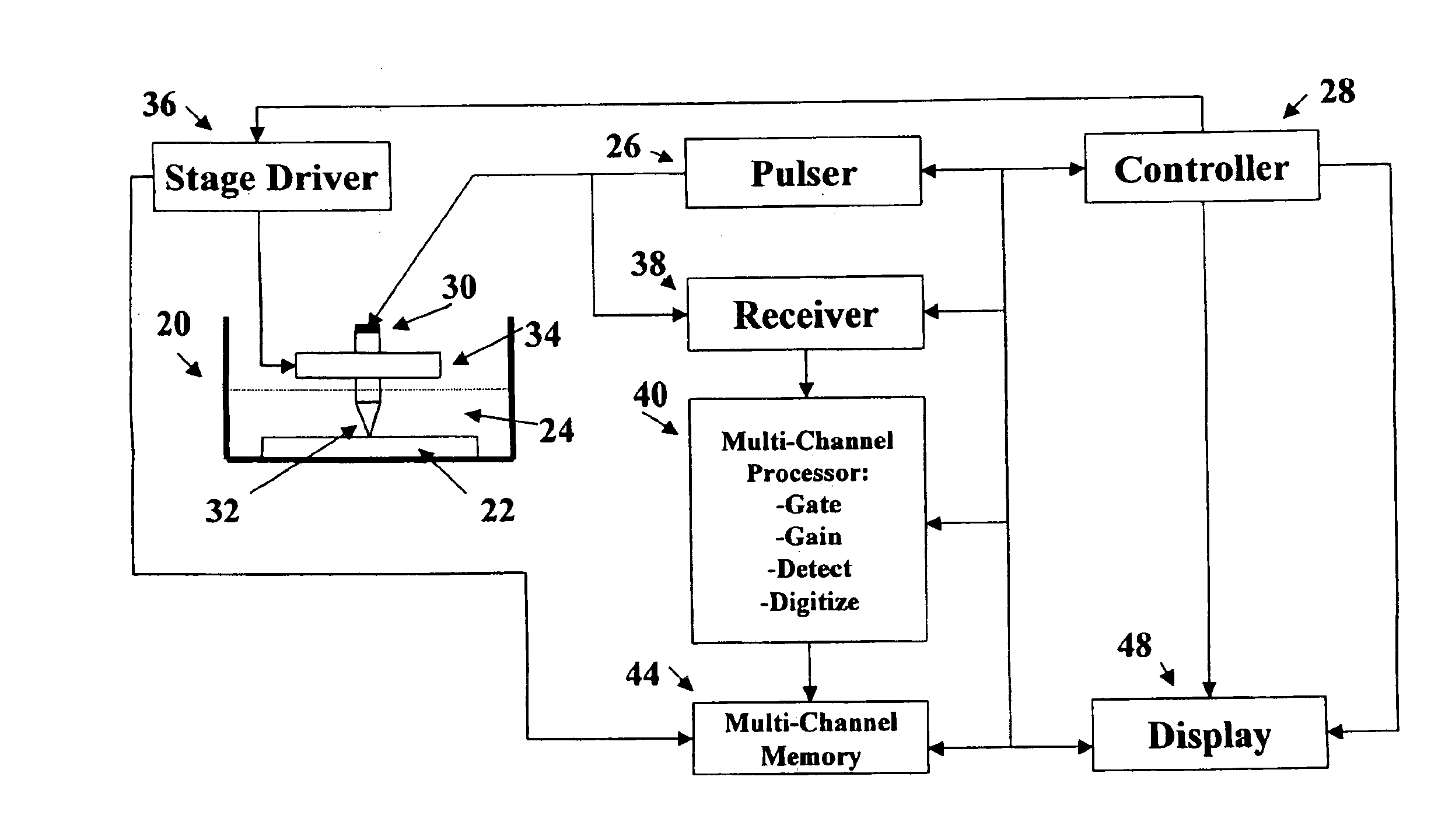
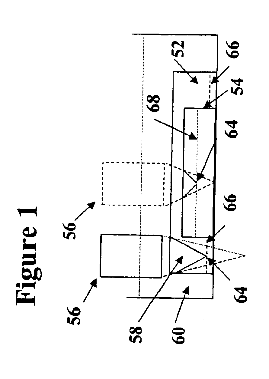
[0008]It is another object of the present invention to meet the described need by providing a method which makes possible the correlation of macro visualizations (such as a full PCB) with micro AMI visualizations, and which in so doing facilitates an improved understanding of interactive effects between spatially separated parts.
[0014]It is a further object to provide display and visualization methods to enhance the information developed from overlays of images developed from like and / or disparate energy forms and techniques.BRIEF

Problems solved by technology

In such applications it is often difficult for the user to physically correlate in space the micro location of the inspected region of interest with the macro space occupied by the sample.
This is extremely valuable information, but it is uncorrelated with the PCB.
Under current practice, AMI inspections are performed on various PCB parts scattered across the board, but no information is available that might suggest a relationship between detected defects or anomalies on various parts.
There is no simple way of predicting whether the placement of a microprocessor or power amplifier or other heat-producing element, for example, is deleteriously affecting the life or performance of adjacent components.

Method used


Image

  • Acoustic micro imaging method providing improved information derivation and visualization
  • Acoustic micro imaging method providing improved information derivation and visualization
  • Acoustic micro imaging method providing improved information derivation and visualization

Examples


Embodiment Construction

[0019]The methods and equipment that has evolved in the field of acoustic micro imaging (“AMI”) has proven to be of great value in non-destructive testing, laboratory research and testing, failure analysis, production quality control and inspection, and many other applications. The ultimate output in most applications is a visual display which is studied to extract the maximum possible information about the interior structure of an examined production part or other sample.

[0020]While a great deal of information can be gleaned from AMI visualizations of acoustic impedance and absorption features within an examined sample, in many applications the capabilities of the AMI equipment and techniques are not fully realized because the spatial context of the visualizations presented are not fully understood. Further, additional useful information can be obtained by interrogating or illuminating the specimen with other forms of energy and correlating that information with acoustically derive...


PUM

PropertyMeasurementUnit
frequenciesaaaaaaaaaa
focal lengthaaaaaaaaaa
frequencyaaaaaaaaaa

Abstract

A method for enhancing information derived from acoustically inspected samples comprises deriving an acoustic image of a sample, and generating a visual superposition of one or more additional images. The additional images are selected from the group consisting of an optical image, a second acoustic image in a different sized field of view form said acoustic image, an infrared image, an X-ray image, and an electron beam image.

Description

BACKGROUND, OBJECTS, AND SUMMARY OF THE INVENTION[0001]This invention has a broad range of applications, however, for convenience of explanation it will be described in the context of what is known as acoustic micro imaging (“AMI”) in which an acoustic microscope is employed to detect minute features within or on the surface of an examined sample. AMI is commonly employed in material and process analysis, failure analysis, non-destructive testing, and production quality control and inspection, for example.[0002]AMI is based upon the fact that acoustic waves traveling through a sample of homogenous material will be altered when the waves encounter an anomaly of some type. If the anomaly has a different acoustic impedance than the sample material, the waves will be reflected, refracted, deflected or scattered. If the anomaly has a different acoustic absorption characteristic than the sample material, a differential absorption of the acoustic wave will occur. Under certain conditions t...

Claims


Application Information

Patent Timeline
Patent Type & Authority Patents(United States)
IPC IPC(8): G01N29/38G01N29/06G01N29/36G01S15/89G01S15/00
CPCG01N29/0681G01S15/8993G01N29/38
Inventor KESSLER, LAWRENCE W.ADAMS, THOMAS E.ORAVECZ, MICHAEL G.
Owner NORDSON CORP
Learn More