Eureka AIR delivers breakthrough ideas for toughest innovation challenges, trusted by R&D personnel around the world.

Mechanical amplifier systems and methods

a technology of mechanical amplifiers and amplifiers, applied in the direction of force measurement, electric/magnetic measuring arrangements, instruments, etc., can solve the problem of long gauge length of lmu, and achieve the effect of increasing the gauge length, and reducing the cost of construction

Inactive Publication Date: 2005-04-19
WELLS FARGO BANK NAT ASSOC +1
View PDF5 Cites 21 Cited by
  • Summary
  • Abstract
  • Description
  • Claims
  • Application Information

AI Technical Summary

Benefits of technology

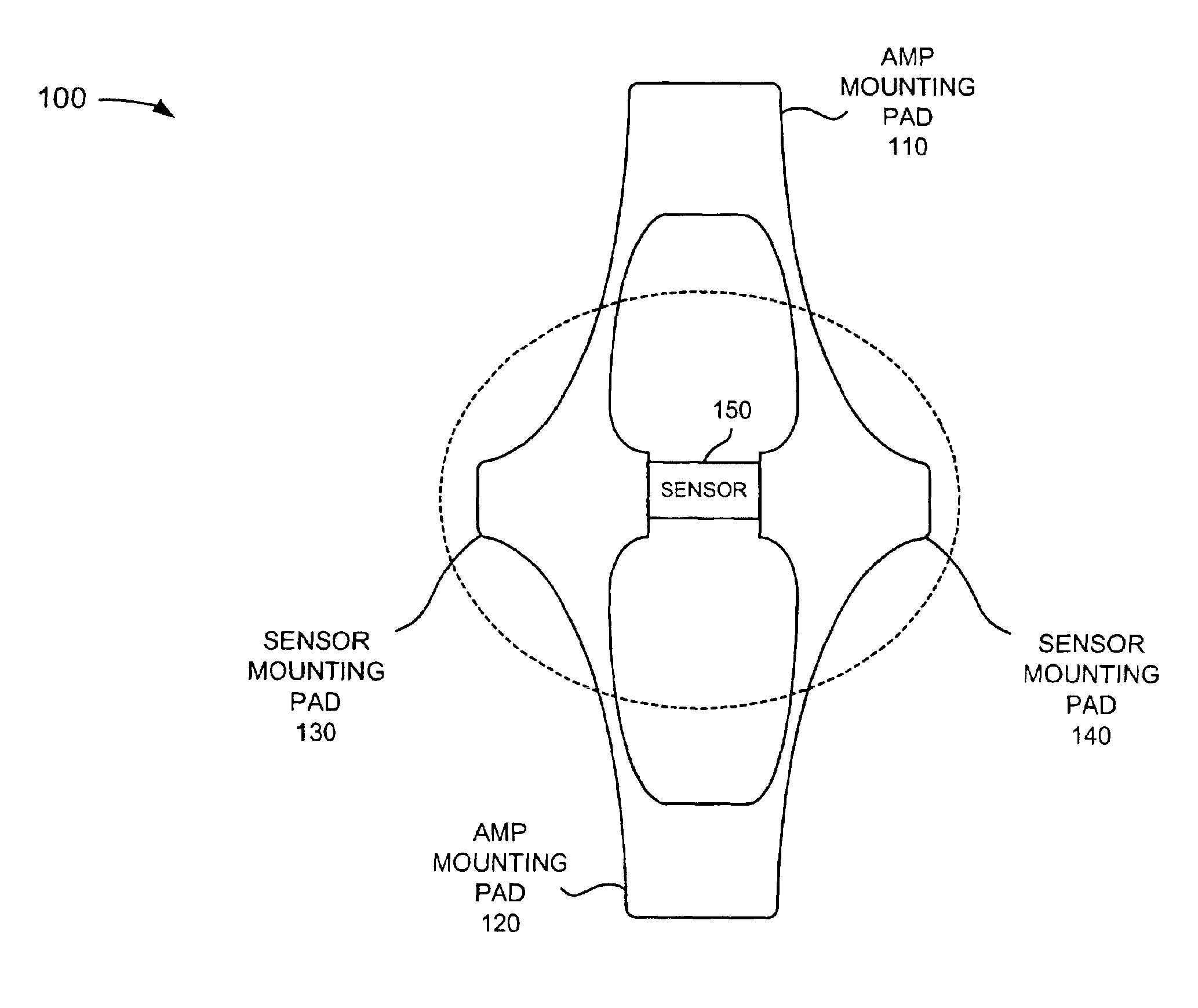
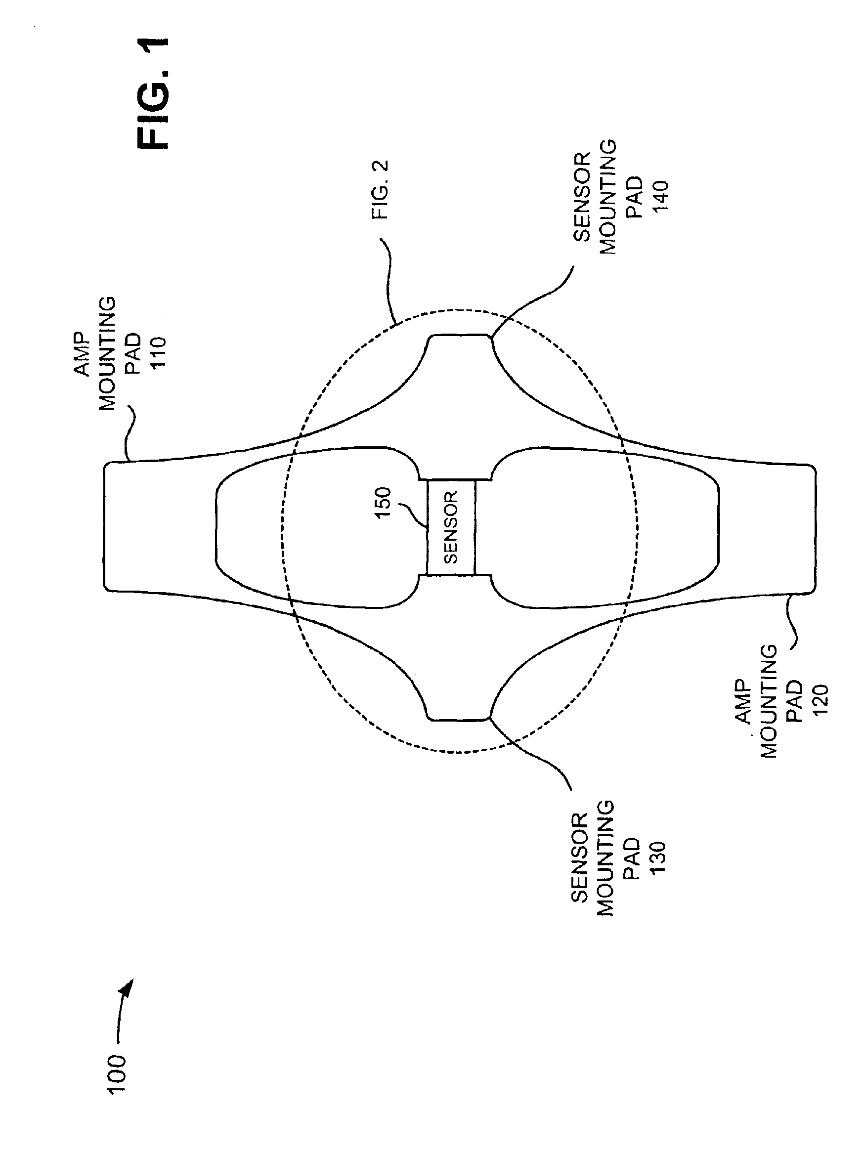
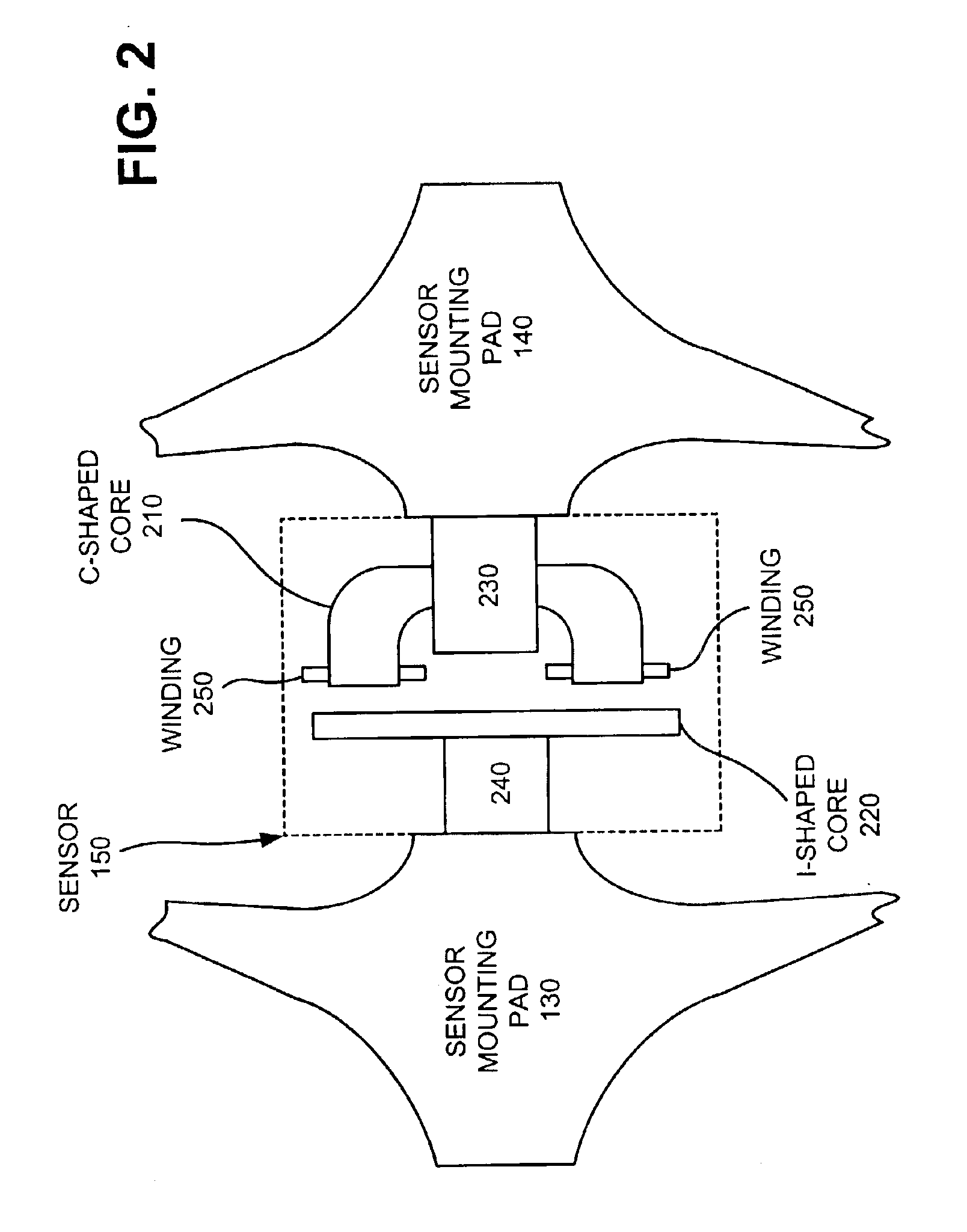
The present invention provides a mechanical amplifier that can increase the gauge length of a load carrying member, allowing for a shorter device while maintaining the same precision. The amplifier includes mounting pads and sensor mounting pads connected via flexible connecting members, which measure the displacement of the load carrying member in both the axial and lateral directions. The load monitoring device can determine the load associated with the load carrying member using multiple rings and a sensor. The load cell includes an upper end cap, a lower end cap, a housing, and one or more mechanical amplifiers with flexible connecting members and a sensor for measuring the load. The invention allows for improved load monitoring and measurement.

Problems solved by technology

Due to limitations typically associated with displacement sensors, the gauge length of the LMU needs to be long to provide sufficient displacement to accurately measure these load-related features.

Method used


Image

  • Mechanical amplifier systems and methods
  • Mechanical amplifier systems and methods
  • Mechanical amplifier systems and methods

Examples


Embodiment Construction

[0026]The following detailed description of the invention refers to the accompanying drawings. The same reference numbers in different drawings may identify the same or similar elements. Also, the following detailed description does not limit the invention. Instead, the scope of the invention is defined by the appended claims and equivalents.

[0027]Systems and methods consistent with the present invention provide a mechanical amplifier that measures displacement and magnifies that displacement in a load monitoring device in the direction of the applied load to effectively increase the gauge length of the load monitoring device. As a result, the load monitoring device can be constructed in a shorter length while maintaining the same precision. Reducing the size of the load monitoring device has the double benefit of reducing the cost of fabrication of the load monitoring device and allowing it to be used in situations where there are height restrictions.

Exemplary Mechanical Amplifier

[...


PUM

PropertyMeasurementUnit
gauge lengthaaaaaaaaaa

Abstract

A mechanical amplifier includes first and second amplifier mounting pads (110, 120) and first and second sensor mounting pads (130, 140). At least one of the first and second amplifier mounting pads (110, 120) receives a load or displacement. The first and second sensor mounting pads (130, 140) connect to the first and second amplifier mounting pads (130, 140) via flexible connecting members. A sensor (150) may connect to the first and second sensor mounting pads to measure the amount of load or displacement.

Description

RELATED APPLICATION[0001]This application claims priority under 35 U.S.C. § 119 based on U.S. Provisional Application No. 60 / 375,789, filed Apr. 26, 2002, the disclosure of which is incorporated herein by reference.BACKGROUND OF THE INVENTION[0002]1. Field of the Invention[0003]The present invention relates generally to the measurement of displacement and, more particularly, to mechanical amplifier systems and methods for measuring displacement. Such systems and methods may also be applicable to load monitoring systems and methods.[0004]2. Description of Related Art[0005]Monitoring of the load in load carrying members is very important in some applications. One load monitoring device uses variable reluctance sensors to measure the displacement in the direction of the applied load. The applied load is obtained by multiplying the displacement by the stiffness of the load carrying member. The precision of the measurement as a percentage of full scale load is determined by the ratio of ...

Claims


Application Information

Patent Timeline
Patent Type & Authority Patents(United States)
IPC IPC(8): G01L1/12
CPCG01L1/127
Inventor MADDEN, RICHARDMURRAY, BRUCE STUART
Owner WELLS FARGO BANK NAT ASSOC
Why Eureka
Eureka Blog
Learn More