Method and apparatus for adjusting drop velocity

a drop velocity and drop velocity technology, applied in the direction of printing mechanism, printing, power drive mechanism, etc., can solve the problems of inefficiency in printhead operation, variation of drop velocity, and ink drop velocity optimization, so as to increase the life of the printhead, reduce the heat of the printhead, and increase the throughput level of the printer

Inactive Publication Date: 2005-04-19
FUNAI ELECTRIC CO LTD
View PDF3 Cites 28 Cited by
  • Summary
  • Abstract
  • Description
  • Claims
  • Application Information

AI Technical Summary

Benefits of technology

[0016]An advantage of certain embodiments of the present invention is that the energy used in an ink jet printer printhead is optimized thereby increasing the life of the printhead.
[0017]Another advantage of certain embodiments of the present invention is that the printhead heats less; thus, throughput levels of the printer can increase since the time required to cool a printhead is reduced or eliminated.
[0018]A further advantage of certain embodiments of the present invention is that variations that occur in the manufacture of the printhead can be compensated.

Problems solved by technology

Because the same predetermined amount of energy is used for each printhead, the energy is not optimized for a particular printhead.
One problem with this manner of ink delivery is that variations in printheads lead to inefficiencies in printhead operation.
The result is ink drop velocity variations and difficulty in maintaining nominal head temperatures.
Another problem is that driving ink jet heater elements at an energy level required to jet ink at an acceptable drop velocity means overdriving some printheads.
By overdriving printheads, the overdriven nozzles can fail prematurely due to electromigration of the heater element.

Method used


Image

  • Method and apparatus for adjusting drop velocity
  • Method and apparatus for adjusting drop velocity
  • Method and apparatus for adjusting drop velocity

Examples


Embodiment Construction

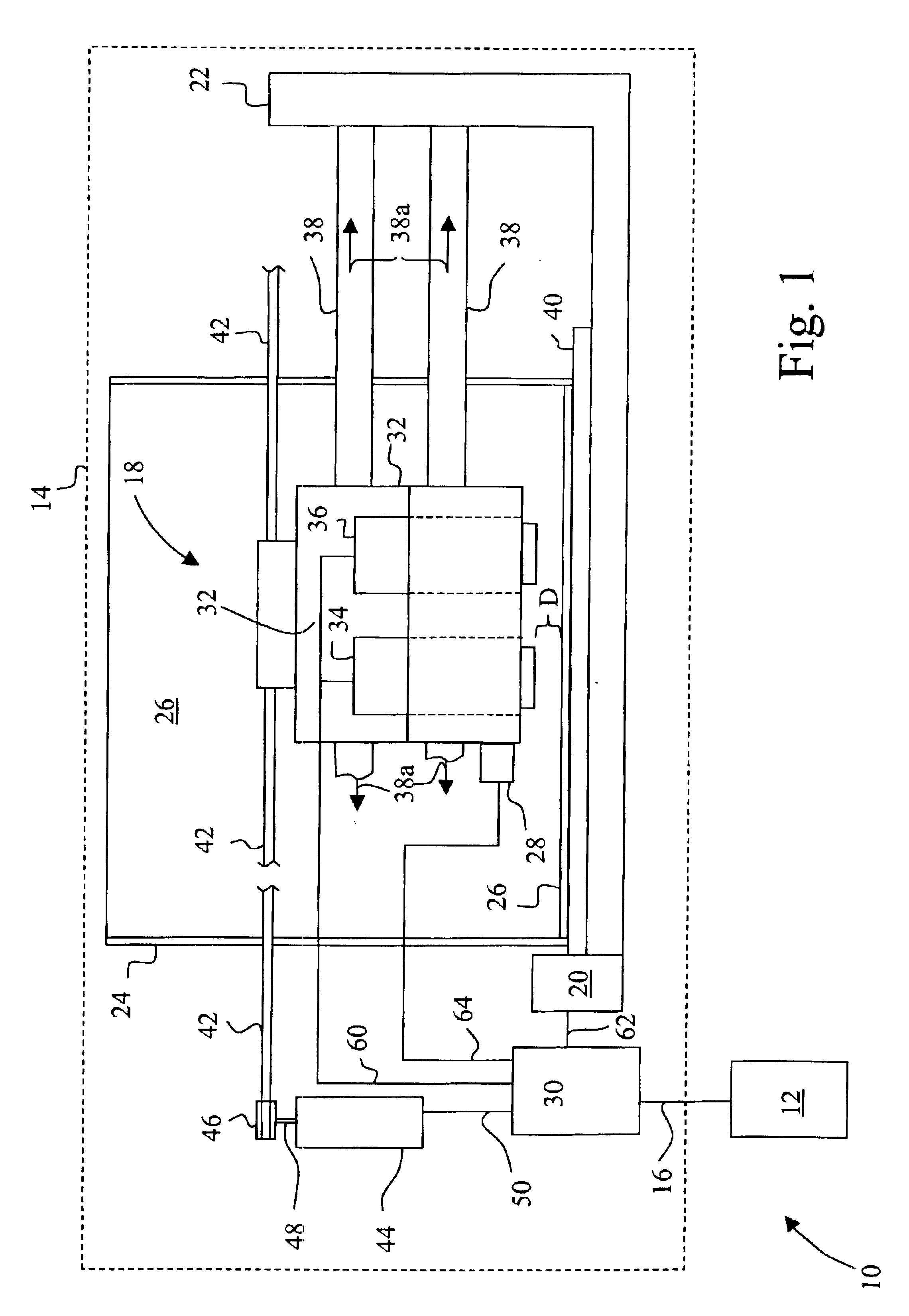
[0027]Referring now to the drawings, and more particularly to FIG. 1, there is shown an imaging system 10 embodying the present invention. Imaging system 10 includes a computer 12 and an imaging device in the form of an ink jet printer 14. Computer 12 is communicatively coupled to ink jet printer 14 by way of a communications link 16. Communications link 16 may be, for example, an electrical, an optical or a network connection.

[0028]Computer 12 is typical of that known in the art, and includes a display, an input device such as a keyboard, a processor and associated memory. Resident in the memory of computer 12 is printer driver software. The printer driver software places print data and print commands in a format that can be recognized by ink jet printer 14.

[0029]Ink jet printer 14 includes a carrier system 18, a feed roll unit 20, a frame 22, a media source 24 holding a sheet of print medium 26, a sensor 28 and a controller 30. In some embodiments, printer 14 might also have a sen...


PUM


Abstract

In an ink jet printer, a method of selecting an optimized energy level associated with a target ink drop velocity including the acts of: moving a printhead across a print medium at a plurality of scan velocities including a first velocity and a second velocity, printing at least one set of patterns on the print medium by supplying at least one predetermined energy level to at least one actuator of the printhead, the at least one set of patterns including a first pattern printed at the first velocity and a second pattern printed at the second velocity, associating the first pattern with the second pattern and selecting the optimized energy level associated with the target ink drop velocity.

Description

CROSS REFERENCE TO RELATED APPLICATIONS[0001]This application includes subject matter related to the co-pending application entitled METHOD FOR DETERMINING INK DROP VELOCITY OF CARRIER-MOUNTED PRINTHEAD, application Ser. No. 10 / 175,972, filed Jun. 20, 2002, and the application entitled METHOD AND APPARATUS FOR OPTIMIZING A RELATIONSHIP BETWEEN FIRE ENERGY AND DROP VELOCITY IN AN IMAGING DEVICE, application Ser. No. 10 / 304,148, filed Nov. 25, 2002, each of which are incorporated by reference herein.BACKGROUND OF THE INVENTION[0002]1. Field of the Invention[0003]The present invention relates to a method and apparatus for adjusting ink drop velocity, and, more particularly, in one embodiment, to a method and apparatus for adjusting ink drop velocity irrespective of sensors.[0004]2. Description of the Related Art[0005]An ink jet printer typically includes a printhead, which is carried by a carrier. The printhead is fluidly coupled to an ink supply. Such a printhead includes a plurality ...

Claims


Application Information

Patent Timeline
Patent Type & Authority Patents(United States)
IPC IPC(8): B41J2/045
CPCB41J2/04505B41J2/04515B41J2/04573B41J2/0458B41J2/0459B41J2/04591B41J2/2135B41J2/04581B41J25/308
Inventor KING, DAVID G.KROGER, PATRICK L.
Owner FUNAI ELECTRIC CO LTD
Why Eureka
Try Eureka