Eureka AIR delivers breakthrough ideas for toughest innovation challenges, trusted by R&D personnel around the world.

Power supply management in paper-processing machines

Inactive Publication Date: 2005-04-19
HEIDELBERGER DRUCKMASHINEN AG
View PDF7 Cites 0 Cited by
  • Summary
  • Abstract
  • Description
  • Claims
  • Application Information

AI Technical Summary

Benefits of technology

[0004]An object of the present invention is to provide a voltage supply concept for a paper-processing machine, ensuring that when the main and auxiliary drives of a paper-processing machine are operated regeneratively, surplus electric energy can be removed without having to destroy an unnecessarily large amount of electric energy in a chopper.
[0010]However, in times of constantly increasing cost of energy and, consequently, also of electricity it can turn out to be advantageous if the mains voltage transformer has a bidirectional design. In this case, the chopper for removing peak loads can be dispensed with because surplus electric energy can be fed back into the mains supply.

Problems solved by technology

However, the conversion of a DC voltage to another DC voltage involves much more effort than is required when converting an AC voltage to another AC voltage.
Only when this is no longer possible, i.e., when the auxiliary drives of the second voltage level cannot consume enough energy either, is the surplus energy consumed in a chopper for removing peak loads at the first voltage level.
In this case, however, no electric energy needs to be fed back into the mains supply so that the mains voltage transformer needs to feed only unidirectionally in one direction, namely into the printing press.
Therefore, it is clear that the drives and circuits of the third voltage level constantly operate motively, i.e., consume electric energy; regenerative operation is not possible here.
That is, electric energy is only destroyed in the chopper when the energy consumption of the base load and the motively operating drives of a printing press or folding machine is smaller than the energy generation in the regeneratively operated drives.

Method used


Image

  • Power supply management in paper-processing machines
  • Power supply management in paper-processing machines

Examples


Embodiment Construction

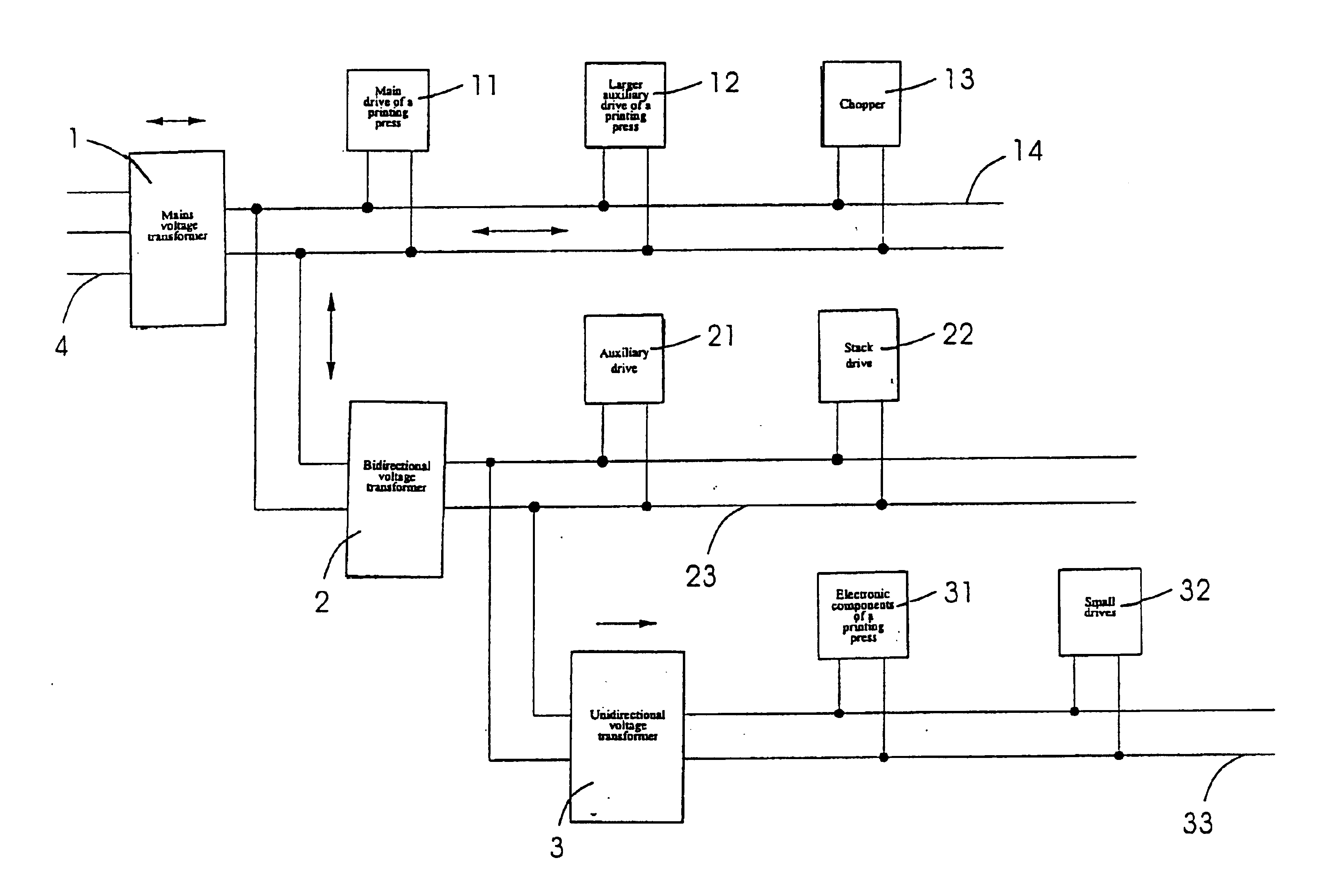
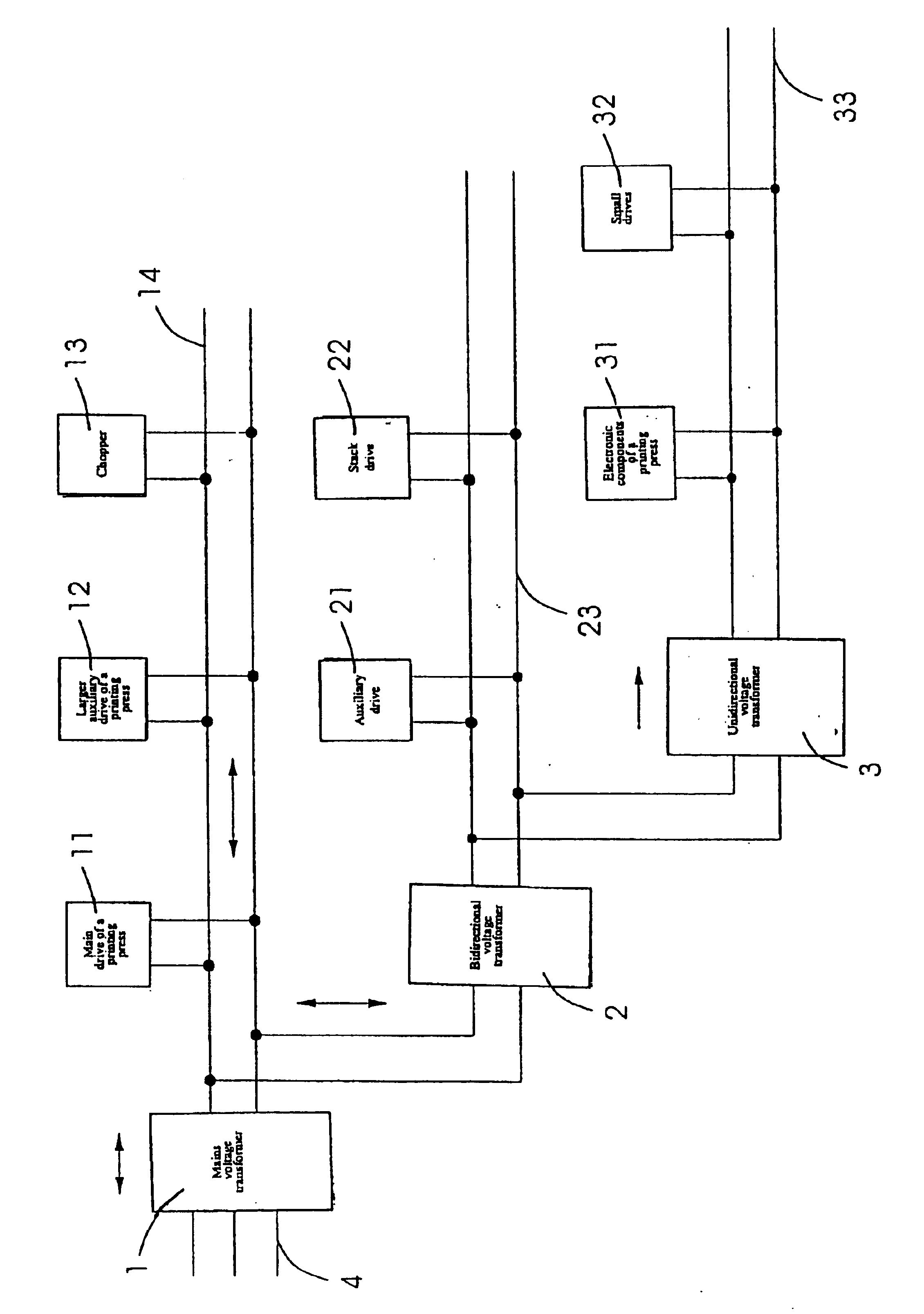
[0013]Paper-processing machines, such as printing presses and folding machines, are usually connected to the 400 Volt three-phase system. This is also true for the voltage supply concept shown in FIG. 1, which is composed of three DC voltage levels of a printing press. In this context, the three-phase current from mains 4 is fed to a voltage transformer 1 which converts the three-phase current to a DC voltage. To this end, voltage transformer 1 is designed either as a diode rectifier or as a half-controlled bridge if it operates unidirectionally, i.e., converts AC voltage from the mains to DC voltage. However, voltage transformer 1 can also be designed as a fully controlled bridge; then it operates bidirectionally and is able to convert both mains voltage to DC voltage and DC voltage to mains voltage. Voltage transformer 1 then allows electric energy to flow from three-phase system 4 into the printing press and vice versa. A first voltage having a value between 400 and 700 Volts is ...


PUM


Abstract

A device for supplying voltage to an electrical machine, in particular a paper-processing machine, having a plurality of electric drives (11, 12, 21, 22, 32), electric drives (11, 12) of the same supply voltage being combined into one voltage level (14, 23, 33). The voltage supply device is characterized in that provision is made for a first DC voltage level (14) having electric drives (11, 12) as well as an electrical component (1, 13) for dissipating surplus electric energy, and provision is made for at least one second DC voltage level (23) which is connected to the first voltage level (14) via a bidirectional voltage transformer (2) and has further electric drives (21, 22), and one of the voltage levels (14, 23) is connected to the mains supply (4) via a voltage transformer (1).

Description

[0001]Priority to German Patent Application No. 102 01 765.4, filed Jan. 18, 2001 and hereby incorporated by reference herein, is claimed.BACKGROUND INFORMATION[0002]The present invention relates to a device for supplying voltage to an electrical machine, in particular a paper-processing machine, having a plurality of electric drives, electric drives of the same supply voltage being combined into one voltage level.[0003]Printing presses and folding machines have a plurality of electric drives. In this context, the power of the electric drives is of different orders of magnitude, depending on the task an electric drive has. So, first of all, there are the main drive and larger auxiliary drives of a printing press, which have powers in the range of 1-100 KW. Below that, in terms of power, come the smaller auxiliary drives and the drives for actuating the stacks at the feeder and the delivery, having powers of several hundred watts. A further group is constituted by the small drives wi...

Claims


Application Information

Patent Timeline
IPC IPC(8): H02J1/08H02J1/00
CPCH02J1/08H02M2001/008H02M2001/007H02J2001/008H02J1/082H02M1/007H02M1/008
Inventor KLEIBAUMHUETER, KLAUS DIETERMEYER, HELMUT
Owner HEIDELBERGER DRUCKMASHINEN AG
Why Eureka
Eureka Blog
Learn More