Connection device for positional fixing of a gradient coil assembly of a nuclear magnetic resonance tomograph

a technology of nuclear magnetic resonance tomograph and connection device, which is applied in the direction of measurement device, magnetic measurement, instruments, etc., can solve the problems of large noise exposure of up to more than 100 decibels, complex positioning and mounting of the gradient coil assembly, and inability to achieve the effect of easy to obtain

Inactive Publication Date: 2005-04-19
SIEMENS AG
View PDF9 Cites 10 Cited by
  • Summary
  • Abstract
  • Description
  • Claims
  • Application Information

AI Technical Summary

Benefits of technology

[0014]The object of the present invention is to provide a connection device for the positional fixing of a gradient coil assembly in an basic field magnet assembly of a nuclear magnetic resonance tomograph, which fixing is simple and easy to obtain.
[0019]If the clamp element is now clamped in the intervening space between the gradient coil assembly and basic field magnet assembly, a wedge effect is produced by the two cited surfaces. This leads to a stiffening of the gradient coil assembly. The result is a minimization of oscillation of the gradient coil assembly, and, in addition thereto, as a consequent of a noise reduction.
[0022]However, this contact surface can naturally only comprise portions of the internal surface of the clamp element and / or the external surface of the gradient coil assembly. This is the case when the internal surface of the clamp element protrudes in the intervening space between the gradient coil assembly and the basic field magnet assembly. This can, for example, provide technical production advantages.

Problems solved by technology

The occurring forces are so great that considerable noise exposures of up to more than 100 decibels occur for a person in the nuclear magnetic resonance tomograph during the measurement.
Due to the use of a plurality of wedges, the positioning and mounting of the gradient coil assembly is relatively elaborate and time-intensive.
The previously cited disadvantage can also occur here, since the forces discretely effect the gradient coil assembly.

Method used


Image

  • Connection device for positional fixing of a gradient coil assembly of a nuclear magnetic resonance tomograph
  • Connection device for positional fixing of a gradient coil assembly of a nuclear magnetic resonance tomograph

Examples


Embodiment Construction

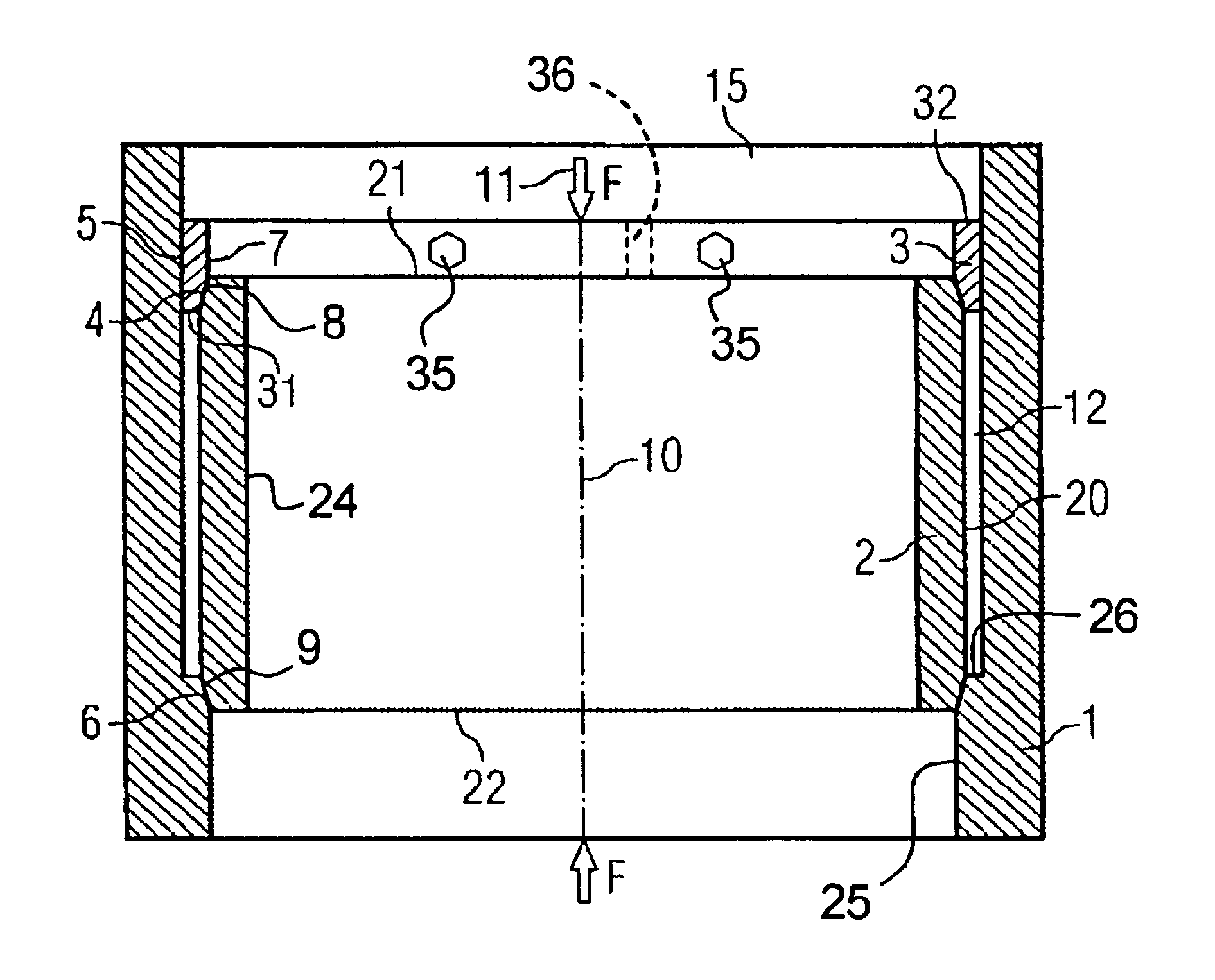
[0035]The principles of the present invention are particularly useful when incorporated in a connecting device for holding a gradient coil assembly 2 in a fixed position in a basic field magnetic assembly 1.

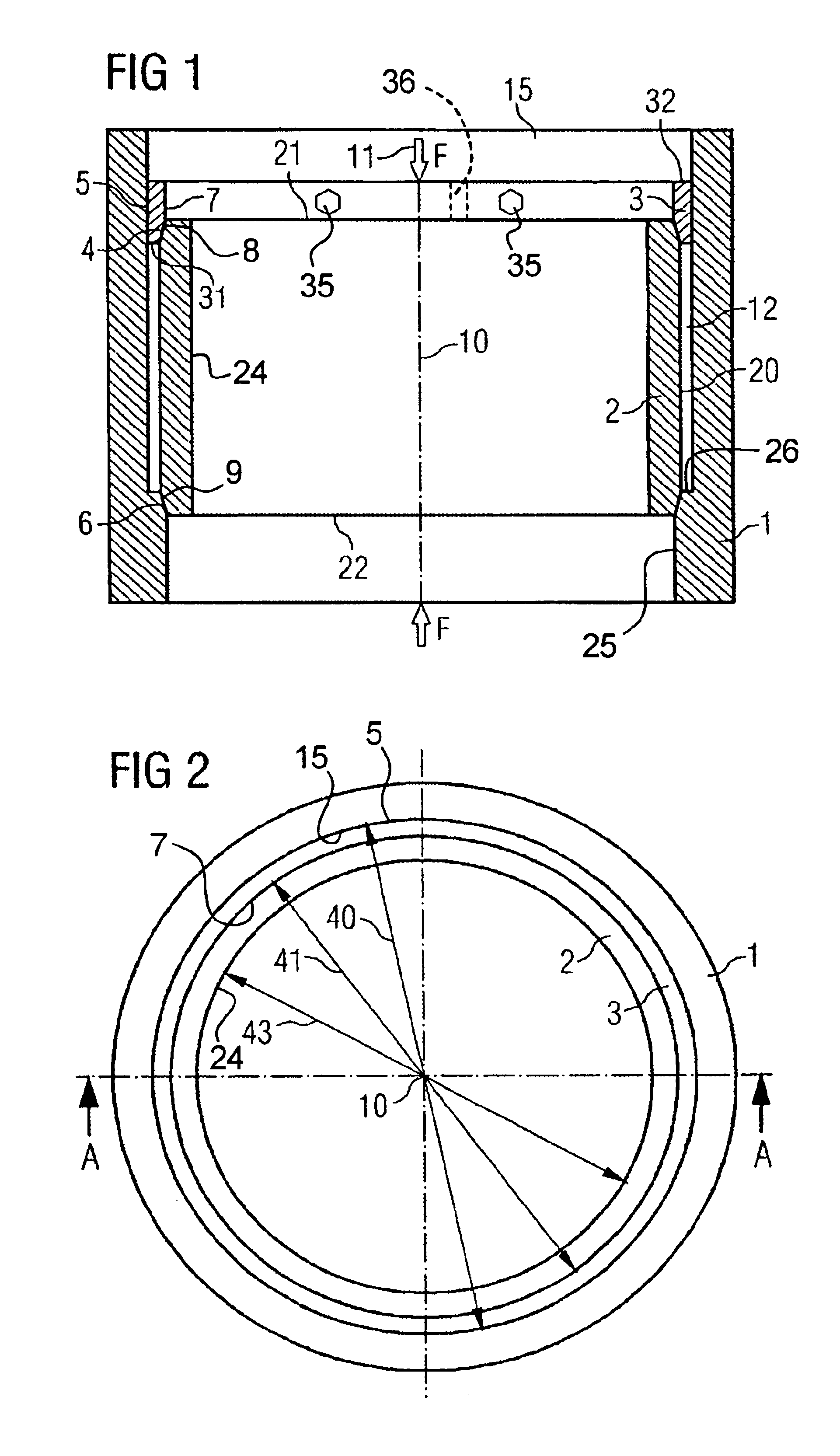
[0036]The gradient coil assembly 2 is a cylindrical body having a cylindrical outer or external surface 20, a first end surface 21, a second end surface 22 and an inner surface 24 with a diameter 43 (see FIG. 2). Adjacent the first end surface 21, the outer surface 20 has a conical surface 4 and also has a conical surface 6 adjacent the opposite end surface 22.

[0037]The basic field magnet assembly 1 has a first internal surface 15, which is cylindrical, with an internal diameter 40 (see FIG. 2) and a second cylindrical surface 25 of a smaller diameter, so as to produce a shoulder 26 therebetween. As illustrated, the shoulder 26 has a corner removed to form a conical internal surface 9.

[0038]A clamping element 3 is illustrated as a substantially cylindrical ring-shaped member havi...


PUM


Abstract

To position and fix the gradient coil assembly in a basic field magnet assembly of a nuclear magnetic resonance tomograph, an annular clamp element is clamped on a surface of the gradient coil assembly between the gradient coil assembly and the basic field magnet assembly. The clamp element has a conical internal surface which is form-fittingly in contact with a similar surface of the gradient coil assembly, so as to provide a self-centering force on the gradient coil assembly and to maintain the gradient coil assembly with an annular gap between the external surface of the gradient coil surface and the interior surface of the basic field magnet assembly.

Description

BACKGROUND OF THE INVENTION[0001]The present invention is directed to a connection device for positional fixing of a gradient coil assembly in a basic field magnet assembly of a nuclear magnetic resonance tomograph. The invention is also directed to devices with components that are comparable to those cited. For example, the invention is also applicable in principle when it concerns an assembly that comprises a plurality of tube-shaped segments in a gradient coil assembly.[0002]In particular, the invention is not limited to devices whose relevant components have the designations “gradient coil assembly” and “basic field magnet assembly”. Thus the invention also concerns as a matter of course a “magnetic resonance tomograph”, for example. In addition, the invention refers to the use of the specified connection device.[0003]A domain of nuclear magnetic resonance tomography is the diagnosis of illnesses of the central nervous system. In particular, cerebral infarcts and the initial sta...

Claims


Application Information

Patent Timeline
Patent Type & Authority Patents(United States)
IPC IPC(8): G01R33/385G01R33/38
CPCG01R33/3858G01R33/3854
Inventor SCHUSTER, JOHANNSTOCKER, STEFAN
Owner SIEMENS AG
Why Eureka
Try Eureka