
Apparatus and method for precision testing of fiber length using electrostatic collection and control of fibers

a technology of electrostatic collection and fibers, applied in the field of fiber sample testing, can solve the problem of fibers staying longer on the belt, and achieve the effect of greater fiber length measurement accuracy and more precise measurement of fiber length

Inactive Publication Date: 2005-04-19
NORTH CAROLINA STATE UNIV
View PDF11 Cites 2 Cited by
  • Summary
  • Abstract
  • Description
  • Claims
  • Application Information

AI Technical Summary

Benefits of technology

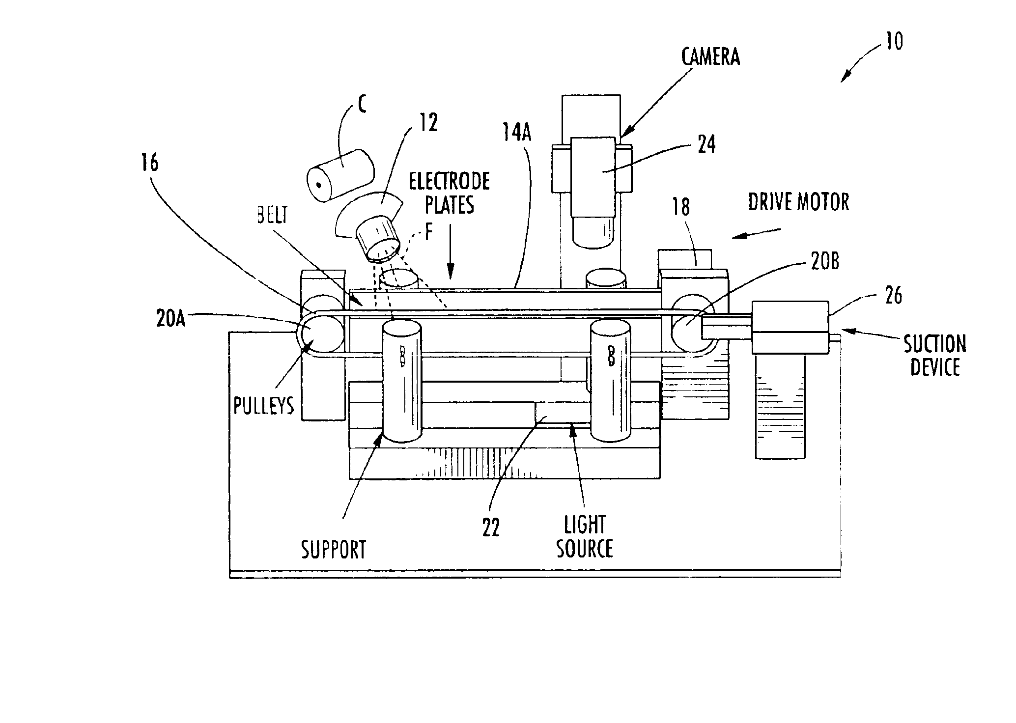
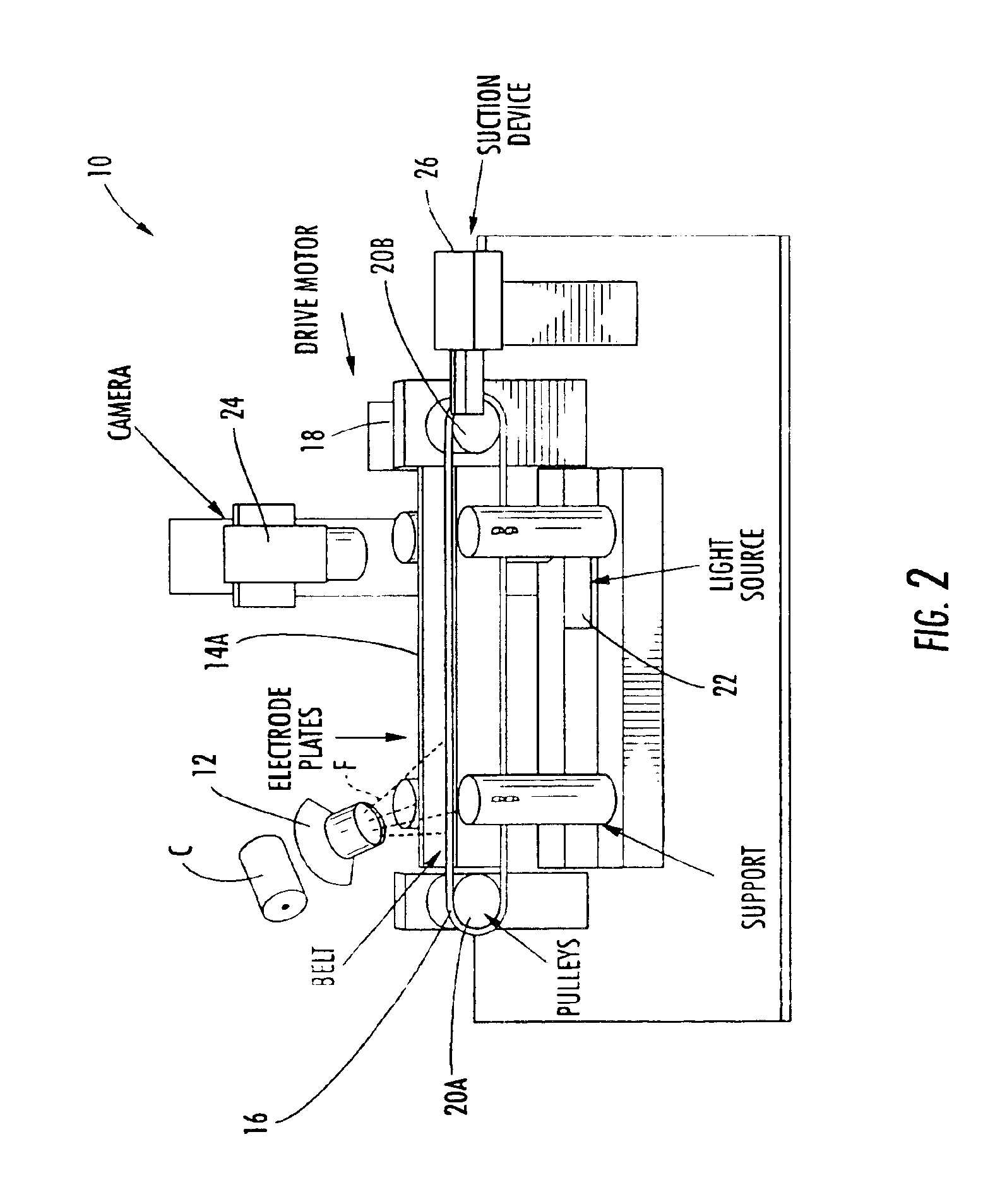
[0015]Also a part of the apparatus is a direct current high voltage source that produces a voltage potential. To one electrode plate the positive terminal of the high voltage source is to be connected, and to the opposing electrode plate the grounded or negative terminal is to be connected. The air space between the electrode plates is to be of such a high resistance that the current between the plates should be close to nonexistent. Since the high voltage is DC, an electrostatic field will have been created going from the positive terminal plate to the grounded or negative terminal plate. Attached to the other side of the electrode plates are support structures. The support structures are to be made of a high resistance material. This serves to isolate the areas of high voltage so that short circuits will not occur to disrupt the electrostatic field, and to minimize the risk of damage to other components and technicians resulting from the high voltage.
[0021]It is another object of the present invention to provide an improved system for collecting and parallelizing fibers for feeding to a digital imaging device and related computer for more precise measurement of fiber length.
[0023]It is still another object of the present invention to provide an apparatus and method that utilizes an electrostatic field to straighten and then move fibers into the area of view of an imaging device in a manner that provides greater fiber length measurement accuracy than has heretofore been possible.

Problems solved by technology

However, fibers will dwell on the belt longer if the resistance of the belt is high.

Method used


Image

  • Apparatus and method for precision testing of fiber length using electrostatic collection and control of fibers
  • Apparatus and method for precision testing of fiber length using electrostatic collection and control of fibers
  • Apparatus and method for precision testing of fiber length using electrostatic collection and control of fibers

Examples


Embodiment Construction

I. General Description

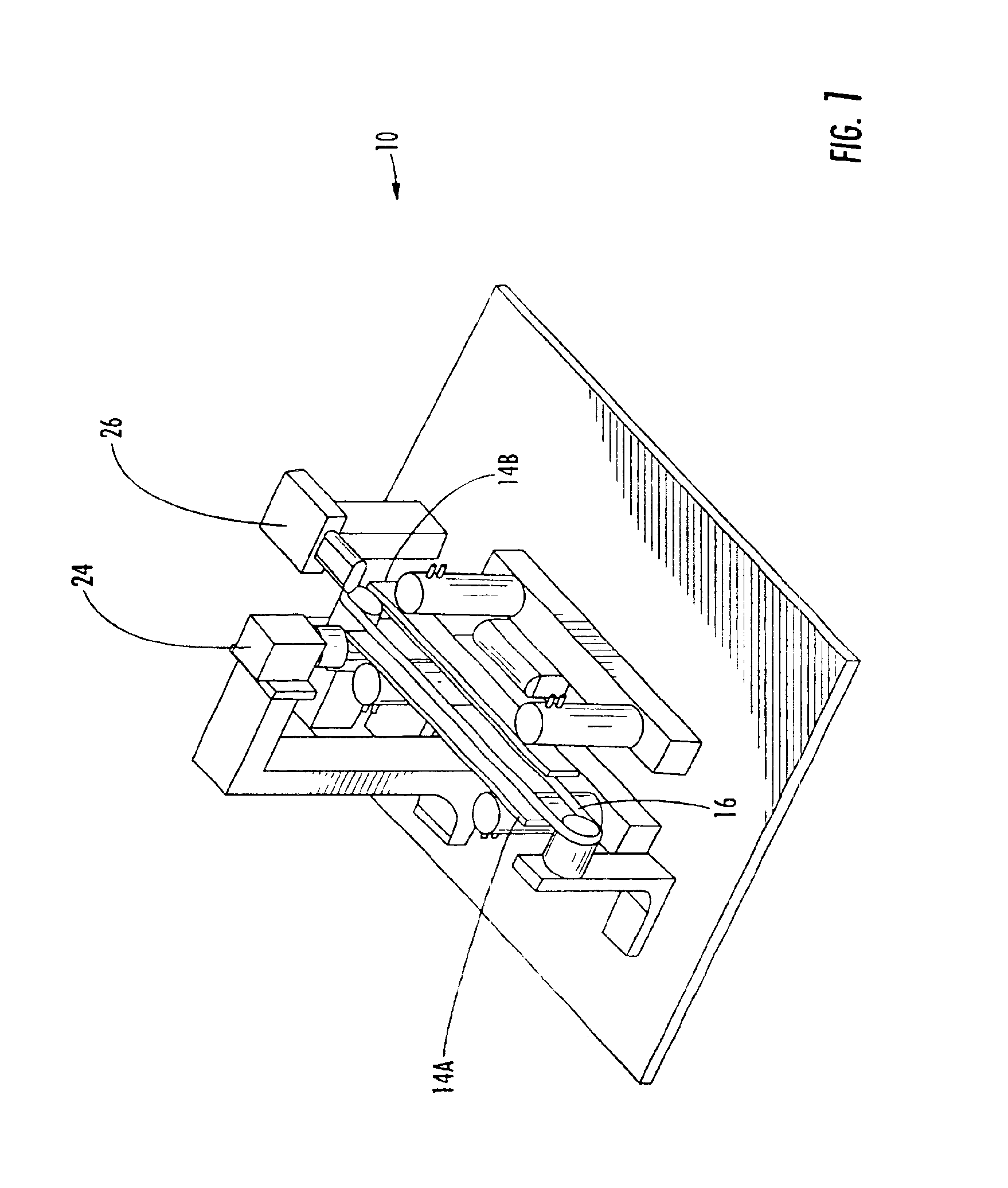
[0036]Referring to FIGS. 1-8, a good overview of the behavior of the apparatus, general designated 10, and the sequence of actions for individual parts can be developed. A fiber F, which has been individualized by a combing roll C, is directed by means of a feed chute 12 into the apparatus 10. As the airborne fibers F float down they come into the region between two opposing electrode plates 14A, 14B. The two opposing electrode plates have an electrostatic field between them that creates an induced charge on the fiber. As the fiber moves downward it becomes attracted to a belt 16, which is driven by a motor 18 connected to pulleys 20B. As the movement of belt 16 continues onward it takes the fiber F along with it until it reaches a region of image taking. At this place between the two opposing electroplates a light source 22 is projected upward from underneath belt 16. Light source 22 creates a back lighting condition for the fibers F in this region, and allows...


PUM


Abstract

A system for precision testing of fiber length and the like using electrostatic collection and control of fibers. The system comprises two spaced-apart and longitudinal extending electrode plates wherein one electrode plate has a positive charge and the other electrode plate is grounded or has a negative charge. An endless rotating belt extends between and parallel to the electrode plates, and the rotating belt is positioned next adjacent and in contact with or in close proximity to one of the two spaced-apart electrode plates such that the distance between the belt and the other electrode plate is greater than the length of fibers to be tested. A fiber introduction system is provided to introduce a plurality of individual fibers above the two electrode plates such that the fibers will adhere to the belt and the other ends of the fibers are attracted to the other electrode plate and thereby straightened. An imaging system is provided above the belt to generate image data corresponding to the length of individual fibers being transported by the rotating belt, and a data processor serves to analyze the image data to determine the length of fibers passing beneath the imaging system.

Description

FIELD OF THE INVENTION[0001]The present invention relates generally to the testing of fiber samples and, more particularly, to precision testing of fiber length utilizing electrostatic collection and control of fibers during image analysis.RELATED ART[0002]Testing of fiber samples, such as, but not limited to, cotton, is important for determining the market value of a particular batch of material, as well as for determining a suitable usage and what processing may be required in gins or spinning mills. Today, nearly 100% of the cotton grown in the United States is classed employing testing instruments. Testing includes determining such characteristics as fiber length, as well as the content of undesired textile entities such as trash and neps.[0003]As a relatively early example, a comb-like device for preparing a sample of ginned cotton for measuring the fiber length thereof is disclosed in HERTEL U.S. Pat. No. 2,404,708, which issued in 1946. That same inventor later developed what...

Claims


Application Information

Patent Timeline
IPC IPC(8): G01B11/02G01N33/36G01N21/88G01N21/89
CPCG01B11/022G01N33/362G01N21/8914
Inventor RUST, JON P.STROUPE, STEPHEN P.BYRD, THESLEY A.BRENZOVICH, JOSEPH A.
Owner NORTH CAROLINA STATE UNIV
Learn More