Pulse width position modulator and clock skew synchronizer

Inactive Publication Date: 2005-04-19
MONTEREY RES LLC
View PDF7 Cites 4 Cited by
  • Summary
  • Abstract
  • Description
  • Claims
  • Application Information

AI Technical Summary

Benefits of technology

[0011]Accordingly, a need remains for printing video image data at high subpixel frequencies without increasing the native clock frequency and more accurately synchronizing printer circuitry with asynchronous line synchronization signals.SUMMARY OF THE INVENTION
[0012]A pulse width position modulator (PWPM) includes a digital delay circuit that outputs multiple subclocks according to a native pixel clock. The multiple subclocks are each skewed to different phases of the native clock. A skew pulse generator receives the multiple subclocks from the digital delay circuit and outputs multiple subpixels according to different logical combinations of the multiple subclocks thereby providing increased subpixel output resolution using the native pixel clock frequency.
[0014]Registers clock the subpixels input to the skew pulse generator. A first set of registers supply a first half of the subpixels to the skew pulse generator after a falling edge of the native pixel clock and a second set of registers supply a second half of the subpixels to the skew pulse generator after a rising edge of the native pixel clock. The registers eliminate race conditions between the native pixel clock and the subpixels.

Problems solved by technology

If the desired subpixel frequency is higher than the clock frequency in which the printing device technology can support, the subpixels are very difficult to generate.
Thus making it difficult to generate subpixels at many desired subpixel frequencies.
Accurate synchronization between the native pixel clock and the LS signal is often not possible using the systems described above because of the high sampling rate required to accurately detect the LS signal.
Because Carley cannot increase subpixel resolution without increasing the frequency cell clock, high resolution subpixel output is not possible.
Further, the analog ramp generators in Carley are expensive and less consistent in different operating conditions and between different print engines.

Method used


Image

  • Pulse width position modulator and clock skew synchronizer
  • Pulse width position modulator and clock skew synchronizer
  • Pulse width position modulator and clock skew synchronizer

Examples


Embodiment Construction

Pulse Width Position Modulator

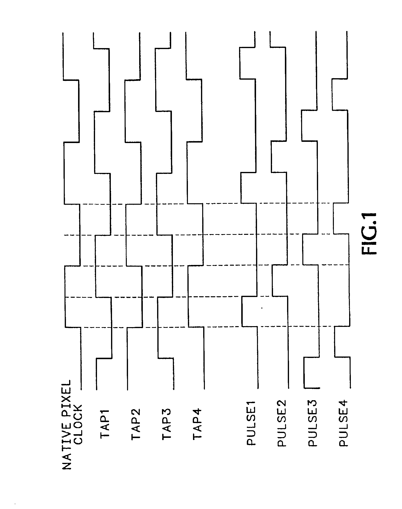
[0026]FIG. 1 shows a native pixel clock signal CLKIN used to generate multiple output subclock waveforms TAP1-TAPN, where for illustrative purposes, N=4. Each subclock is skewed by a different percentage of the CLKIN clock period. The skewed waveforms are used to generate multiple clock pulse trains that control the output of subpixels at resolutions higher than the clock signal. The example shown in FIG. 1 is for a N=4 digital delay line (DDL) circuit that generates four pulse trains PULSE1-PULSE4. The pulse trains PULSE1-PULSE4 control a video data output stream of subpixels for a ¼ subpixel resolution. The system is adaptable to provide any 1 / N subpixel resolution without requiring a higher clock frequency.

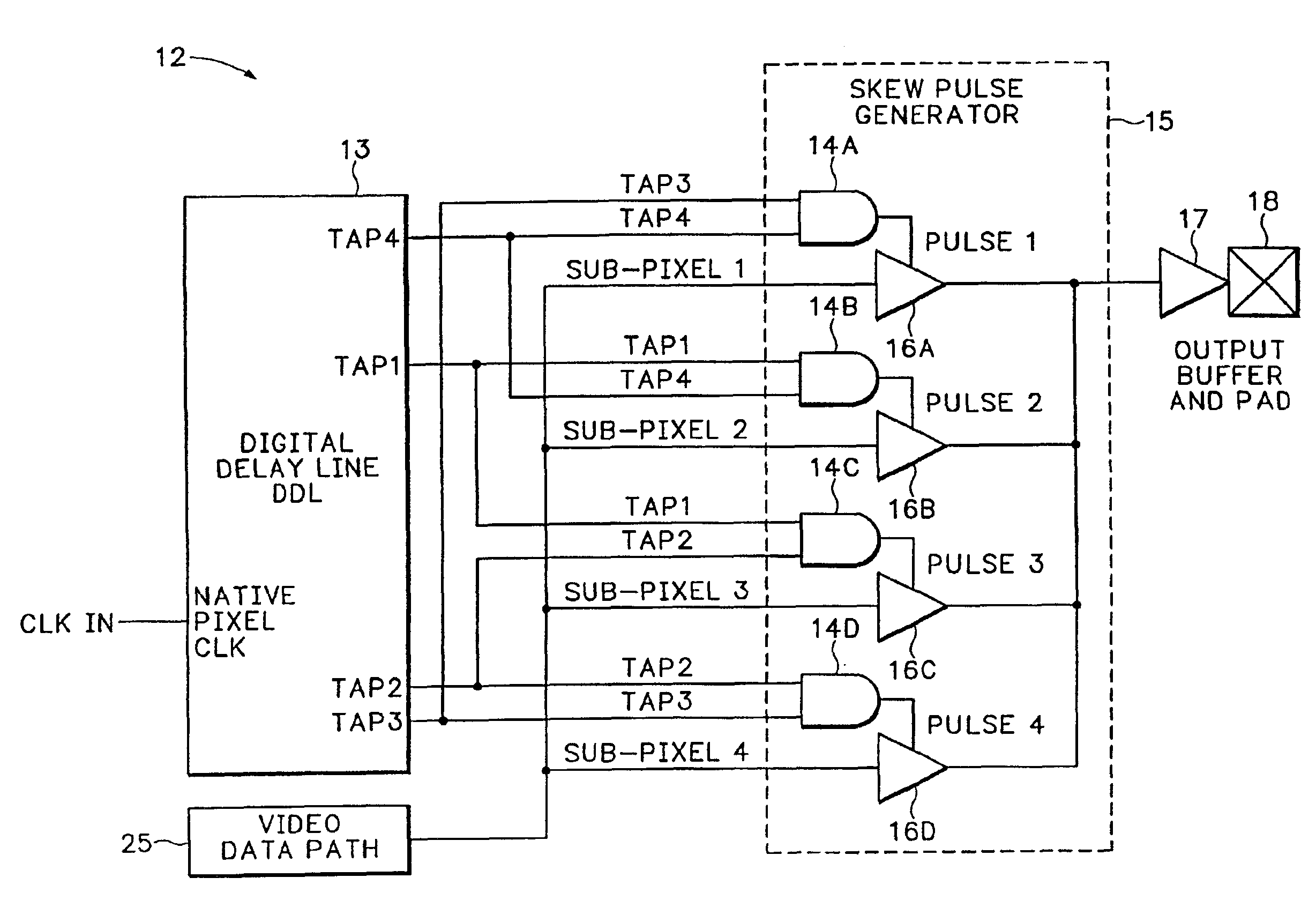
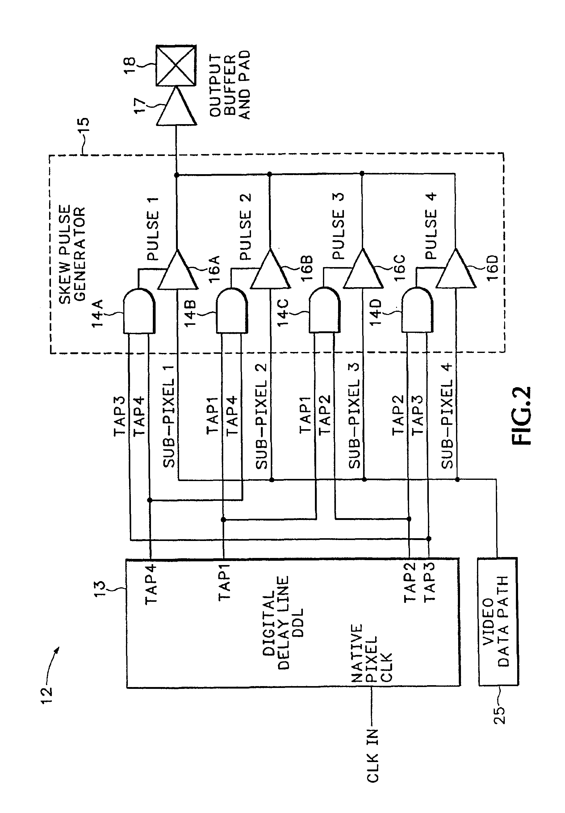
[0027]FIG. 2 shows a Virtual Clock Multiplier (VCM) circuit 12 that produces the four pulse trains shown in FIG. 1. The VCM 12 includes a DDL 13 and a Skew Pulse Generator (SPG) 15. The DDL 13 is an analog device that receives the native pixel cloc...


PUM


Abstract

A pulse width position modulator (PWPM) includes a digital delay circuit that outputs multiple subclocks according to a native pixel clock. The multiple subclocks are each skewed within different time periods of the native pixel clock period. A skew pulse generator receives the multiple subclocks from the digital delay circuit and outputs multiple subpixels according to different logical combinations of the multiple subclocks thereby providing increased subpixel output resolution using the native pixel clock. A clock skew synchronizer aligns the subpixels with a line synchronization signal. The clock skew synchronizer allows lines in a printed image to be aligned with the line synchronization signal within subpixel resolution without using high frequency sampling circuity.

Description

BACKGROUND OF THE INVENTION[0001]This application is a continuation of prior application Ser. No. 09 / 076,754, filed May 12, 1998, which claims benefit of Provisional Appl. No. 60 / 063,827, filed Oct. 31, 1997.[0002]This invention relates to print engines and more specifically to a pulse width position modulation circuit and clock skew synchronizer circuit that generates and synchronizes subpixels without requiring high clock frequencies.[0003]A marking engine is an electromechanical device that takes digital video data and marks a paper media with the image represented by the video data. A native pixel is the inherent single pixel size of the marking engine in a scan direction of, for example, 600 dots per square inch (dpi). A subpixel is a portion (usually 1 / N where N=2M) of a native pixel. Gray-scale is a scale of gray tones graduating from black to white. A gray-scale also denotes tone scales in color.[0004]Marking engines, color or black & white, commonly have little ability to m...

Claims


Application Information

Patent Timeline
IPC IPC(8): H04N1/405
CPCH04N1/4056
Inventor MCDONALD, CALVIN K.
Owner MONTEREY RES LLC
Why Eureka
Try Eureka