

Digital signal receiver
a digital signal and receiver technology, applied in the field of digital signal receivers, can solve the problems of low bit error rate, low accuracy, and the inability of conventional receivers to follow the level of input signal fluctuation at high speed, and achieve the effect of favorable receiving performan
- Summary
- Abstract
- Description
- Claims
- Application Information
AI Technical Summary
Benefits of technology
Problems solved by technology
Method used
Image

Examples
embodiment 1
(Embodiment 1)
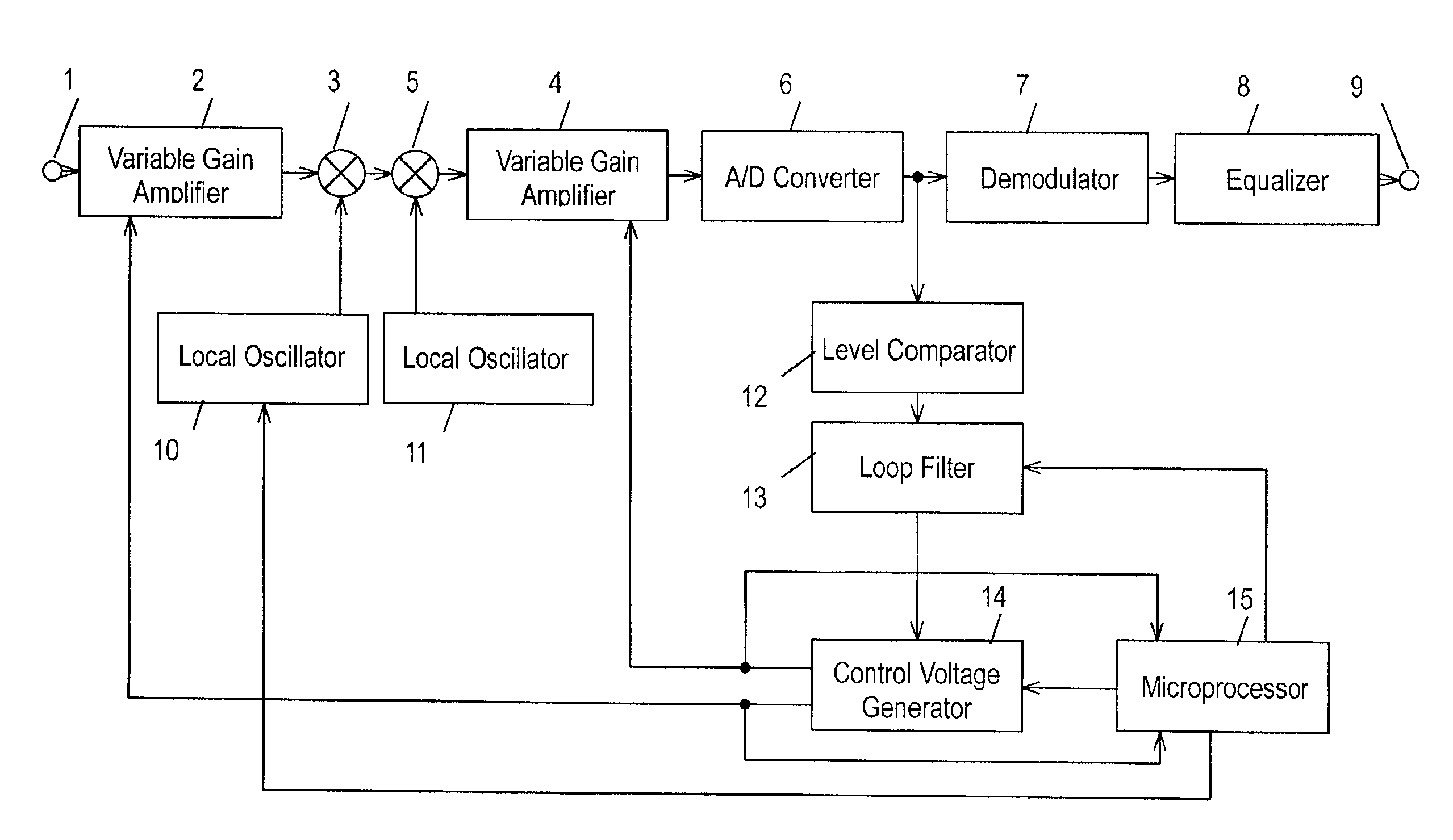
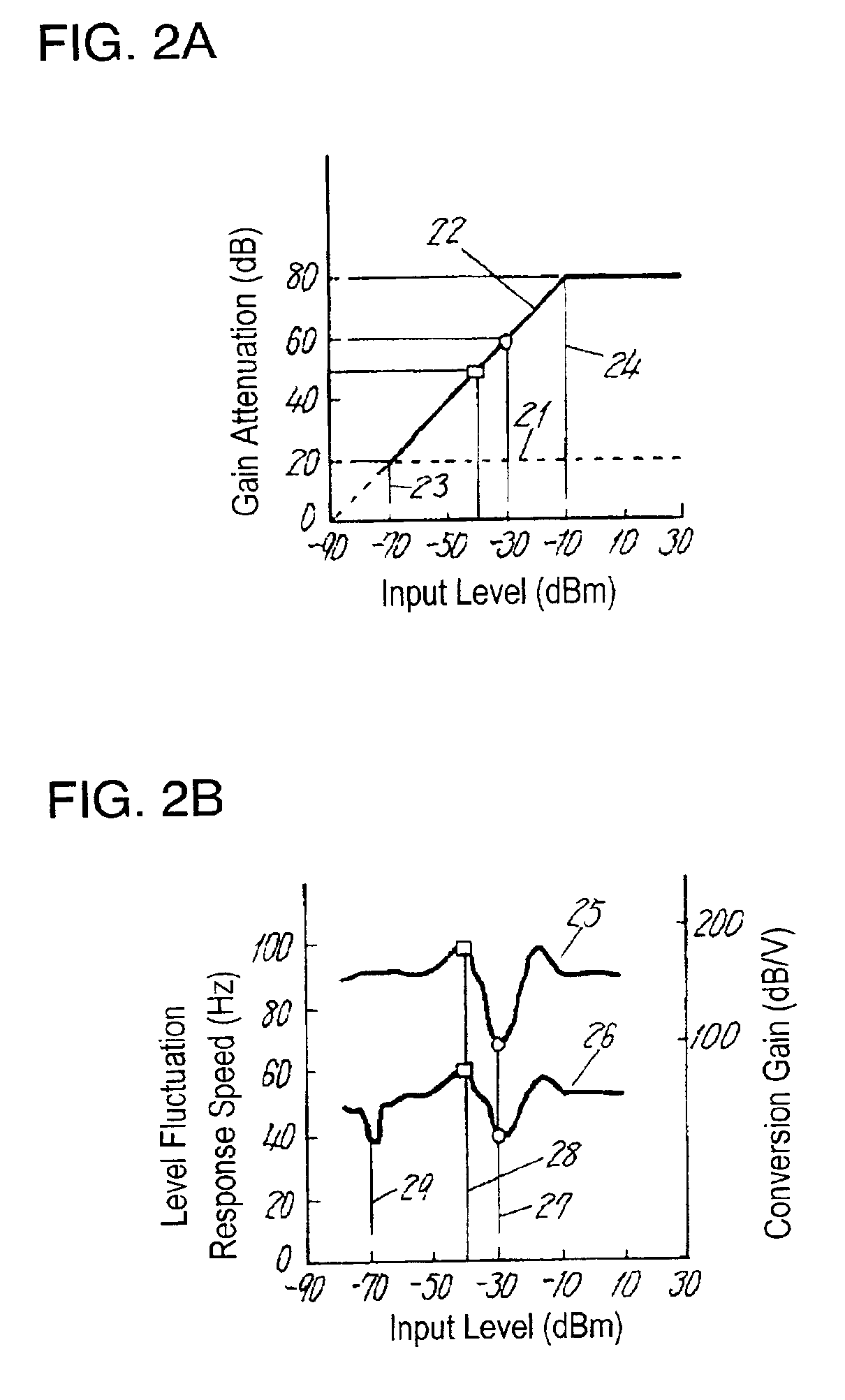
[0028]FIG. 1 is a block diagram of a digital signal receiver according to embodiment 1 of the invention. FIG. 2A shows the relation of an input level to a gain attenuation at a operation-starting point of a variable gain amplifier of −70 dBm. FIG. 2B shows the relation of the input level to a conversion gain, and the input level to a level fluctuation response speed at the operation-starting point of the variable gain amplifier of −70 dBm. FIG. 3A shows the relation of the input level to the gain attenuation at the operation-starting point of the variable gain amplifier of −60 dBm. FIG. 3B shows the relation of the input level to the conversion gain, and input level to the level fluctuation response speed at the operation-starting point of the variable gain amplifier of −60 dBm.
[0029]In the following explanation, a level fluctuation amplitude is ±2 dB unless otherwise noted.
[0030]In FIG. 1, the digital signal receiver comprises input terminal 1 for receiving a digital ...
embodiment 2
(Embodiment 2)
[0040]As shown in FIG. 2B, when the operation-starting point of variable gain amplifier 2 and the input level are same at −70 dBm, the level fluctuation response speed is poor at 40 Hz in spite of the high conversion gain of 90 dB / V In this aspect, when a signal whose level fluctuates is input, the operation point shifts to and from between the operation region and non-operation region of variable gain amplifiers 2 and 4. Accordingly, variable gain amplifiers 2 and 4 must be changed over in real time to the level fluctuations. To change over, microprocessor 15 controls control voltage generator 14 by reading the control voltage, and it takes time. And therefore, it is often difficult to respond quickly to the change.
[0041]In embodiment 2, when the input level and the operation-starting point of variable gain amplifier 2 are close to each other, a response speed for a level fluctuation of 50 Hz is obtained as shown in FIG. 3B by changing the operation-starting point.
embodiment 3
(Embodiment 3)
[0042]As shown in FIG. 2A, in the case of the operation-starting point of variable gain amplifier 2 of −70 dBm, when the input level becomes −10 dBm or more, the gain attenuation of variable gain amplifier 2 saturates due to the dynamic range of amplifier 2. And the gain attenuation cannot be changed however the control voltage generator changes the control voltage. In this region, the bit error rate of the digital broadcast receiver degrades extremely.
[0043]When detecting the input level of −10 dBm or more by the control voltage for controlling the variable gain amplifier, microprocessor 15 controls control voltage generator 14 to change the operation-starting point of amplifier 2 from −70 dBm to −60 dBm. As a result, the relation of the input level to the gain attenuation becomes as shown in FIG. 3A, so that the input of A / D converter 6 is controlled constantly until the input level becomes 0 dBm.
PUM
 Abstract
Description
Claims
Application Information