
Template door and wing assembly with break-away feature for rail ballast regulator

a technology of ballast regulator and wing assembly, which is applied in the direction of snow cleaning, tilling equipment, roads, etc., can solve the problems of ballast disruption, wing assembly often encountering debris or fixed objects, and requiring re-positioning, so as to achieve convenient re-positioning and greater reliability

Inactive Publication Date: 2005-04-26
NORDCO WISCONSIN
View PDF4 Cites 22 Cited by
  • Summary
  • Abstract
  • Description
  • Claims
  • Application Information

AI Technical Summary

Benefits of technology

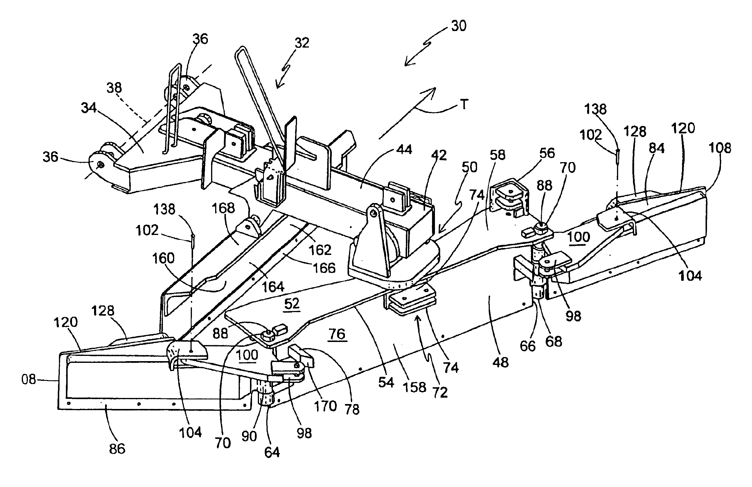
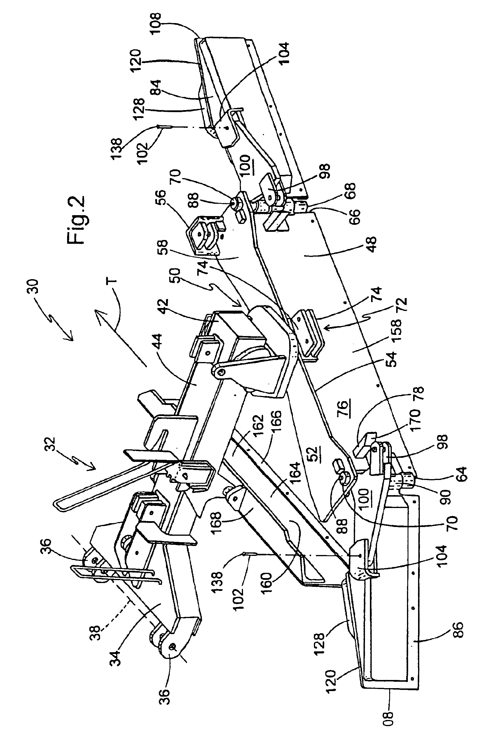
[0009]The above-listed needs are met or exceeded by the present rail ballast template door assembly which overcomes the limitations of the current technology. Among other things, the present assembly features a breakaway joint between the template door and the outer door, which receives the impact force and dissipates it by breaking, causing the template door to swing free of obstacles. The template door can then be easily reattached in the field by installing a new shear pin. In addition, the template doors are preferably provided with strengthened hinge points, support plates and a grader blade for greater reliability. Also, the outer door features a top plate boss which is pivotably sandwiched to an improved top plate assembly.

Problems solved by technology

During railway maintenance operations, including but not limited to tie replacement, rail replacement or the like, the ballast becomes disrupted and must be reshaped.
One disadvantage of conventional rail ballast regulator wing assemblies, is that during operation, the wing assemblies often encounter debris or fixed objects such as culverts, concrete barriers, curbs, rails, concrete construction debris or the like.
Accordingly, when the moving template doors impact fixed obstacles, they often become damaged, misaligned, skewed or otherwise disfigured to the extent that the ballast reconditioning operation must be suspended until repairs can be made.
Due to the remote nature of railway maintenance, repairs are often not easily made.
In some cases, crews arrange for temporary repairs in the field which are often unsatisfactory in the type of ballast reshaping achieved after repair, or in unwittingly increasing the wear and tear on other machine components due to imbalances or misalignments.
In other cases, bent or destroyed template doors are replaced using available materials which do not always achieve desirable ballast reconditioning.
A frequently damaged area is the hinge between the outer door and the template door, which if not repaired correctly, causes poor reconditioning or other operational problems.
Another frequently damaged area is the pivot joint where the outer door is secured to the boom.

Method used


Image

  • Template door and wing assembly with break-away feature for rail ballast regulator
  • Template door and wing assembly with break-away feature for rail ballast regulator
  • Template door and wing assembly with break-away feature for rail ballast regulator

Examples


Embodiment Construction

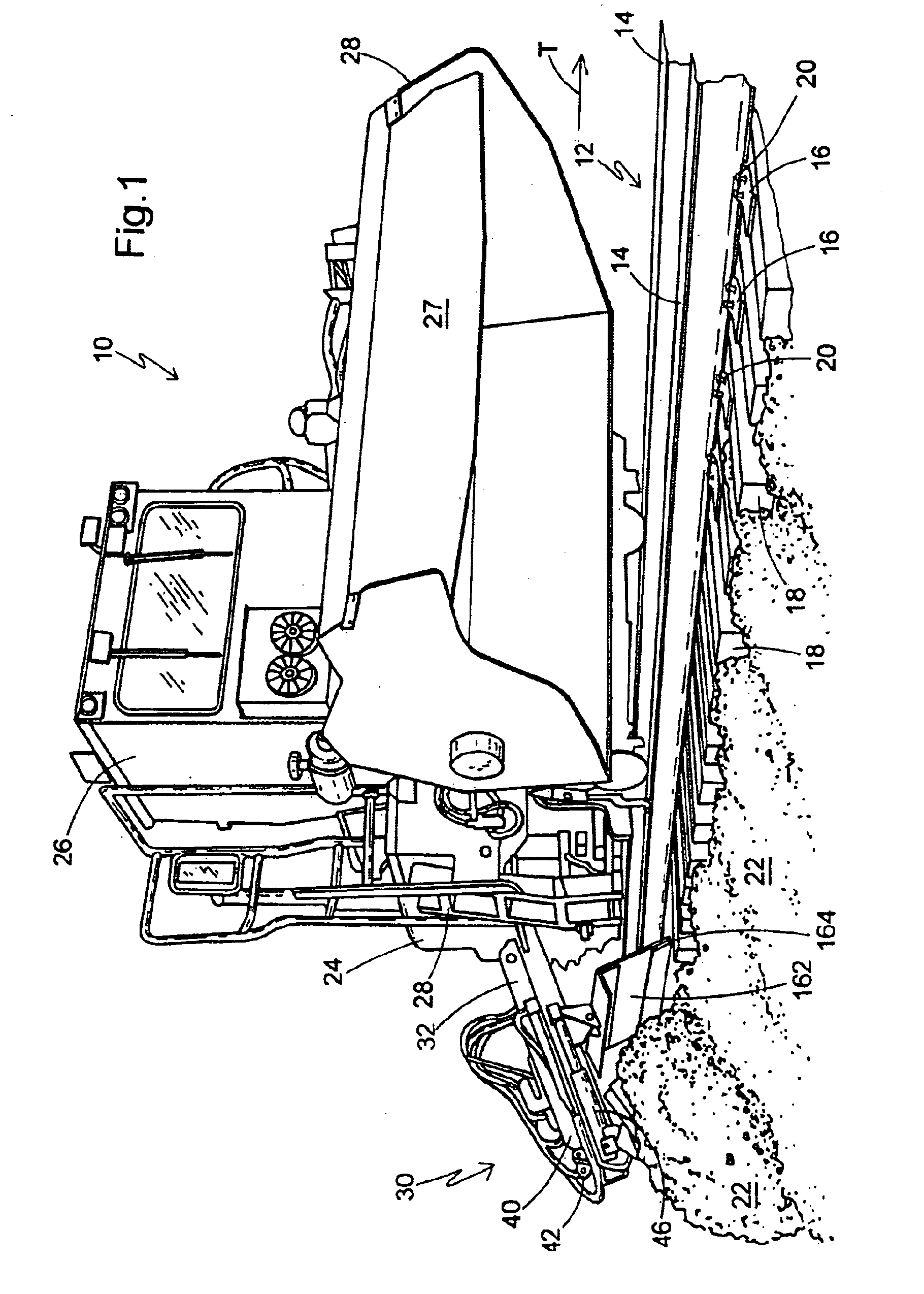
[0020]Referring now to FIG. 1, a railroad ballast regulator, generally designated 10, is shown disposed on a railroad track 12 having a pair of rails 14 mounted on tie plates 16 which are attached to typically wooden ties 18 by fasteners 20 such as rail spikes, lag screws or the like. The ties 18 are supported by particulate ballast 22, which is typically made of crushed rock.

[0021]The regulator 10 is preferably self-propelled through a power source 24 such as a diesel engine, but it is also contemplated that the machine could be towed along the track 12. An operator's cab 26 includes a control panel and other operator inputs (not shown) which are used to control the movement of the regulator 10 along the track 12, as well as the ballast regulating functions which will be described below. A broom 27 is preferably disposed at a rear of the regulator 10 for sweeping ballast 22 from the tops of the ties 18. Each of two sides 28 of the regulator 10 is preferably provided with a rail bal...


PUM


Abstract

A rail ballast wing assembly includes a outer door with at least one hinge edge, a template door pivotably secured to least one of the hinge edges and a positioning device associated with the outer door and the template door for maintaining an angular orientation of the template door relative to the outer door. A breakaway mechanism is connected to the positioning device and the template door and configured for temporarily disengaging the template door from the positioning device upon exposure to impact forces. The breakaway mechanism preferably includes a plate connecting the positioning device to the template door, and being disengageable from the template door. A top pin on the outer door is pivotably secured to a top plate through the use of at least one retainer bracket.

Description

BACKGROUND OF THE INVENTION[0001]The present invention relates generally to railroad right of way maintenance machinery, and specifically to machinery used for forming and / or shaping rail track ballast in conjunction with railroad track repair, replacement or reconditioning.[0002]Crushed rock rail ballast forms the support bed into which rail ties are inserted for receiving tie plates, spikes or other fasteners, and ultimately rail track. Ballast supports the weight of loaded trains, and also is sufficiently porous to remove standing water from the typically wooden ties. Also, the ballast provides the ability to maintain a constant rail / ground displacement or grading over varying terrain and soil conditions.[0003]During railway maintenance operations, including but not limited to tie replacement, rail replacement or the like, the ballast becomes disrupted and must be reshaped. The optimal shape of rail ballast is a generally level upper surface in which the ties are embedded, and a ...

Claims


Application Information

Patent Timeline
IPC IPC(8): E01B27/00E01B27/02
CPCE01B27/02E01B27/025
Inventor FUERST, JAMES WILLIAM
Owner NORDCO WISCONSIN
Learn More