Solenoid valve with improved magnetic attractive force
a solenoid valve and magnetic attractive force technology, which is applied in the field of solenoid valves, can solve the problems of reducing magnetic efficiency, increasing the possibility of damaging the non-magnetic body, and improving the sliding operation of the slider, so as to improve the magnetic attractive force, and reduce the chance of introducing debris and dust.
- Summary
- Abstract
- Description
- Claims
- Application Information
AI Technical Summary
Benefits of technology
Problems solved by technology
Method used
Image
Examples
first embodiment
(First Embodiment)
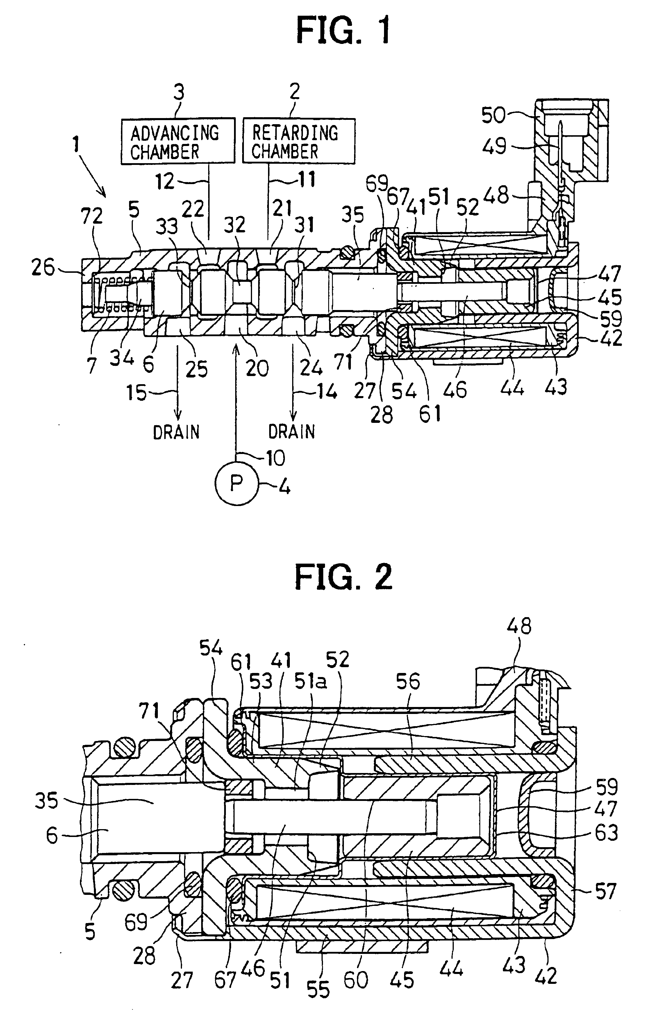
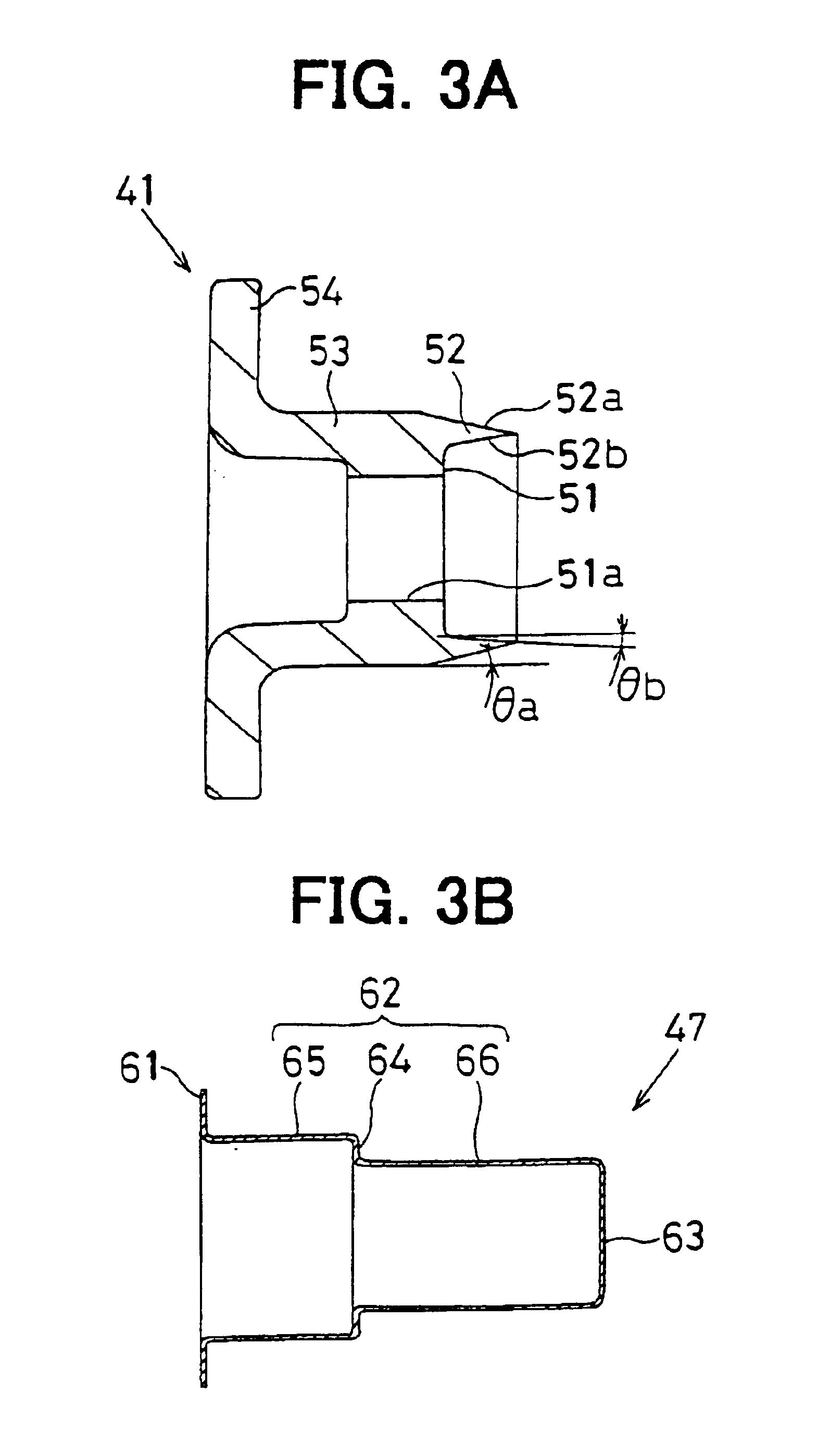
[0029]A first embodiment of the present invention will be described with reference to FIGS. 1 to 5. FIG. 1 is a schematic cross-sectional view of a solenoid-operated oil pressure control valve 1. FIG. 2 is an enlarged cross-sectional view of a main feature of the control valve 1.
[0030]The control valve 1 of the present embodiment is a solenoid valve (Oil Control Valve or simply abbreviated as OCV), which can selectively supplies and drains oil relative to a retarding oil pressure chamber 2 and an advancing oil pressure chamber 3 of a linearly variable valve timing adjusting system. The variable valve timing adjusting system linearly changes opening timing and closing timing (valve timing) of a corresponding intake valve (not shown) arranged, for example, in a cylinder head of a four cycle reciprocating engine (internal combustion engine), such as a double overhead camshaft (DOHC) engine (hereinafter, simply referred to as the engine).
[0031]The variable valve timing...
second embodiment
(Second Embodiment)
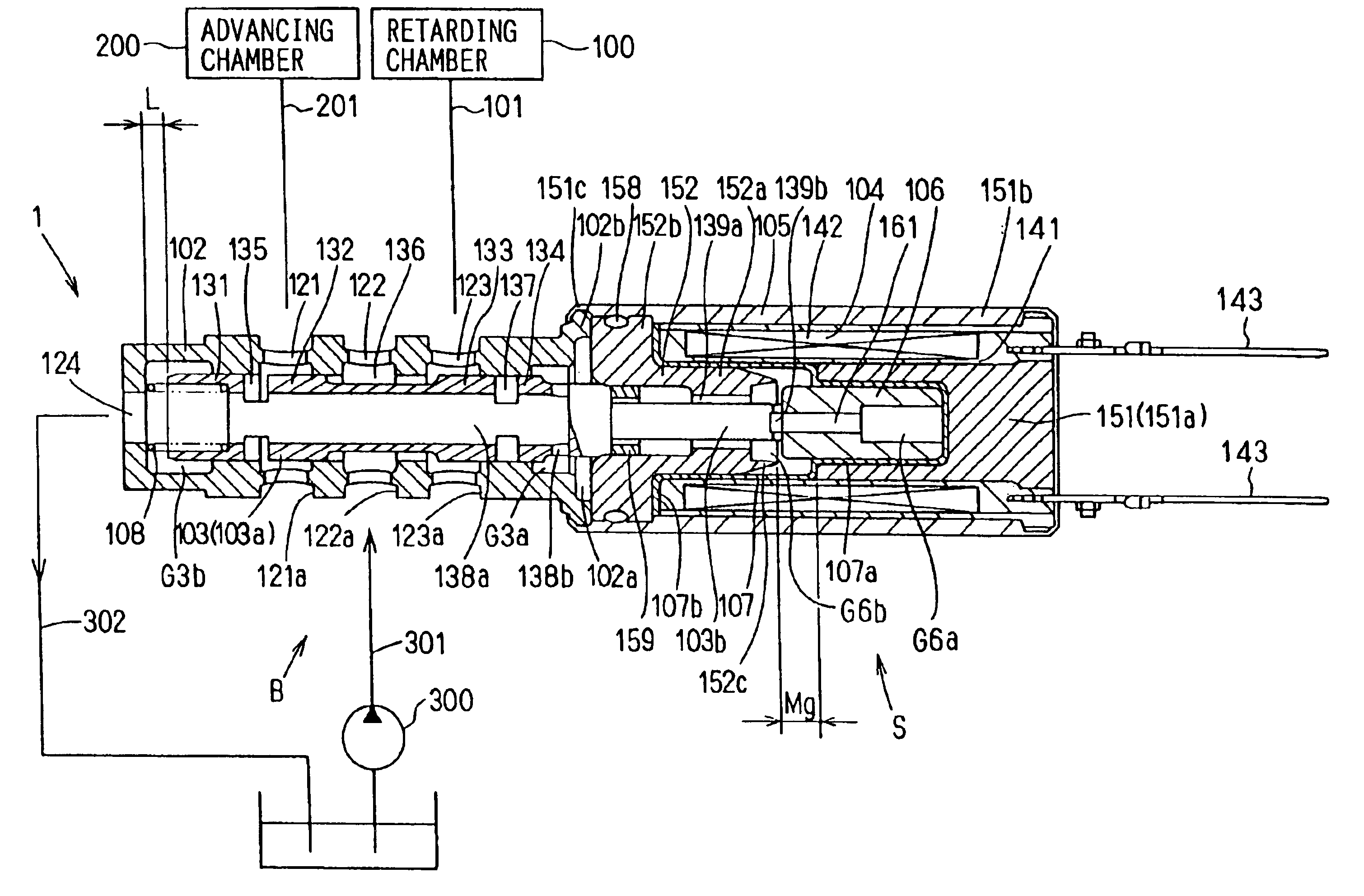
[0067]An oil pressure control valve for a valve timing adjusting system of an internal combustion engine according to a second embodiment of the present invention will be described with reference to FIGS. 6 to 11.
[0068]With reference to FIG. 6, the oil pressure control valve 1 of the present embodiment is a solenoid valve (Oil Control Valve or simply abbreviated as OCV). The control valve 1 can selectively supplies and drains oil to a retarding oil pressure chamber 100 and an advancing oil pressure chamber 200 of the variable valve timing adjusting system. The variable valve timing adjusting system linearly changes opening timing and closing timing of a corresponding intake valve (not shown) arranged, for example, in a cylinder head of a four cycle reciprocating engine (internal combustion engine), such as a double overhead camshaft (DOHC) engine (hereinafter, simply referred to as the engine).
[0069]The variable valve timing adjusting system of the present embodim...
PUM
 Abstract
Description
Claims
Application Information
 - R&D
- Intellectual Property
- Life Sciences
- Materials
- Tech Scout
- Unparalleled Data Quality
- Higher Quality Content
- 60% Fewer Hallucinations
Browse by: Latest US Patents, China's latest patents, Technical Efficacy Thesaurus, Application Domain, Technology Topic, Popular Technical Reports.
© 2025 PatSnap. All rights reserved.Legal|Privacy policy|Modern Slavery Act Transparency Statement|Sitemap|About US| Contact US: help@patsnap.com


