Spacer for a long substrate

a spacer and substrate technology, applied in the direction of rigid pipes, flexible pipes, thermal insulation, etc., can solve the problems of not achieving the two necessary goals equally well, requiring very little material but a relatively large amount of space, and achieving good heat insulation properties and enduring high mechanical loads

Inactive Publication Date: 2005-04-26
NEXANS
View PDF18 Cites 9 Cited by
  • Summary
  • Abstract
  • Description
  • Claims
  • Application Information

AI Technical Summary

Benefits of technology

[0012]Thus, an object of the invention is to provide a spacer which is made with little material and consequently has good heat insulating properties and which can withstand high mechanical loads.

Problems solved by technology

The spacers of the prior art have the drawback that they do not implement these two necessary goals equally well.
This design requires very little material but a relatively large amount of space within the insulation area.
Since it is furthermore difficult to fix the thread elements permanently to the rings and the fixation can be loosened under tensile loads, this spacer is less suitable for flexible tube systems where tensile or compression loads of more than 10,000 N may occur during bending.
Although this spacer has great mechanical strength it lacks the necessary insulating properties.

Method used


Image

  • Spacer for a long substrate
  • Spacer for a long substrate
  • Spacer for a long substrate

Examples


Embodiment Construction

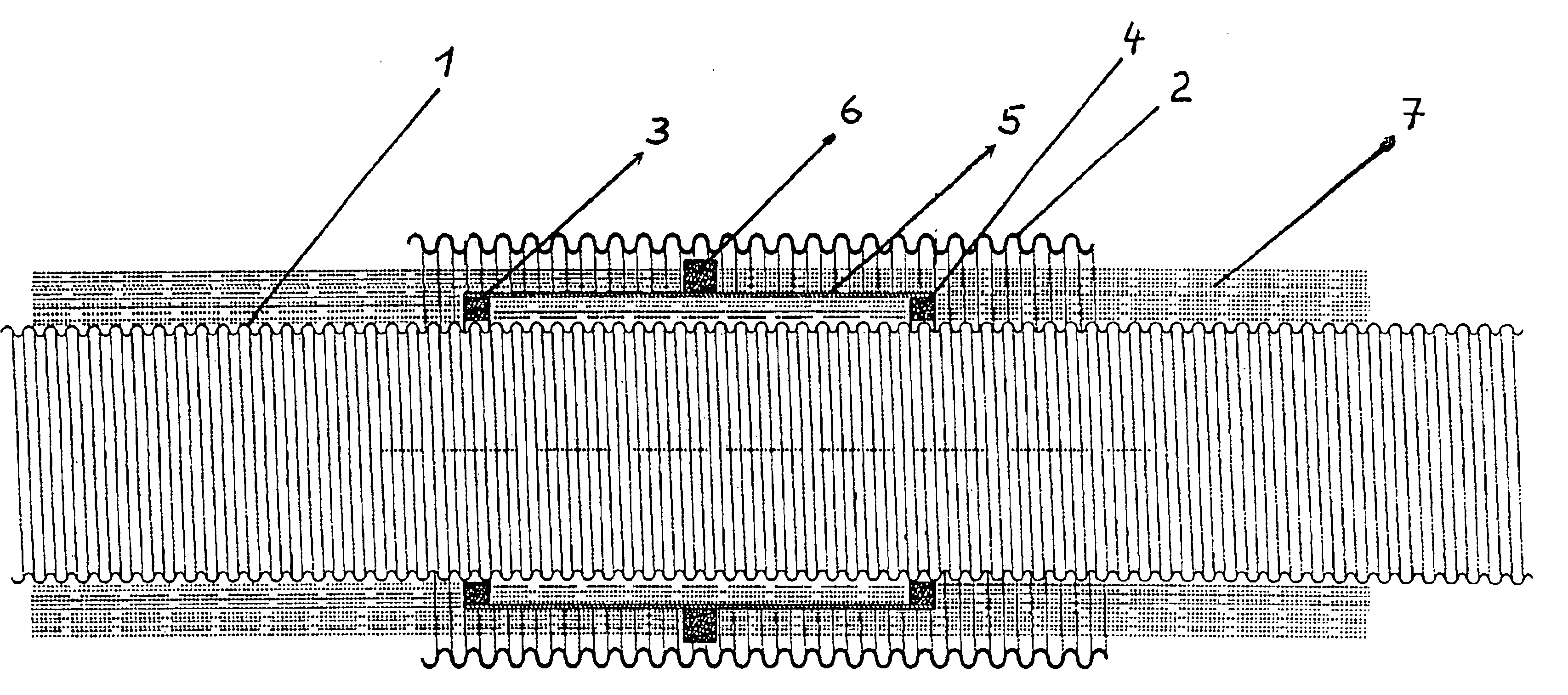
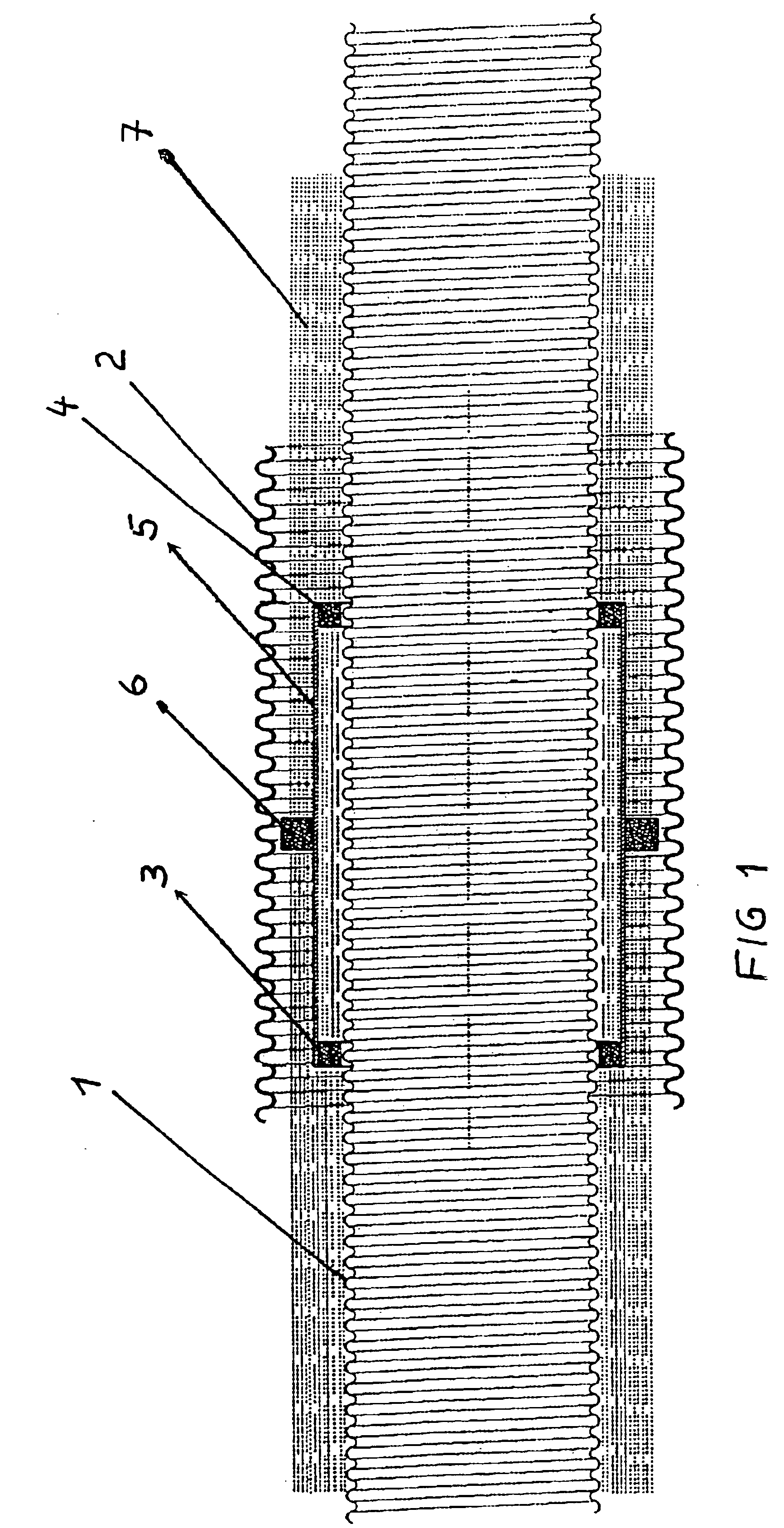
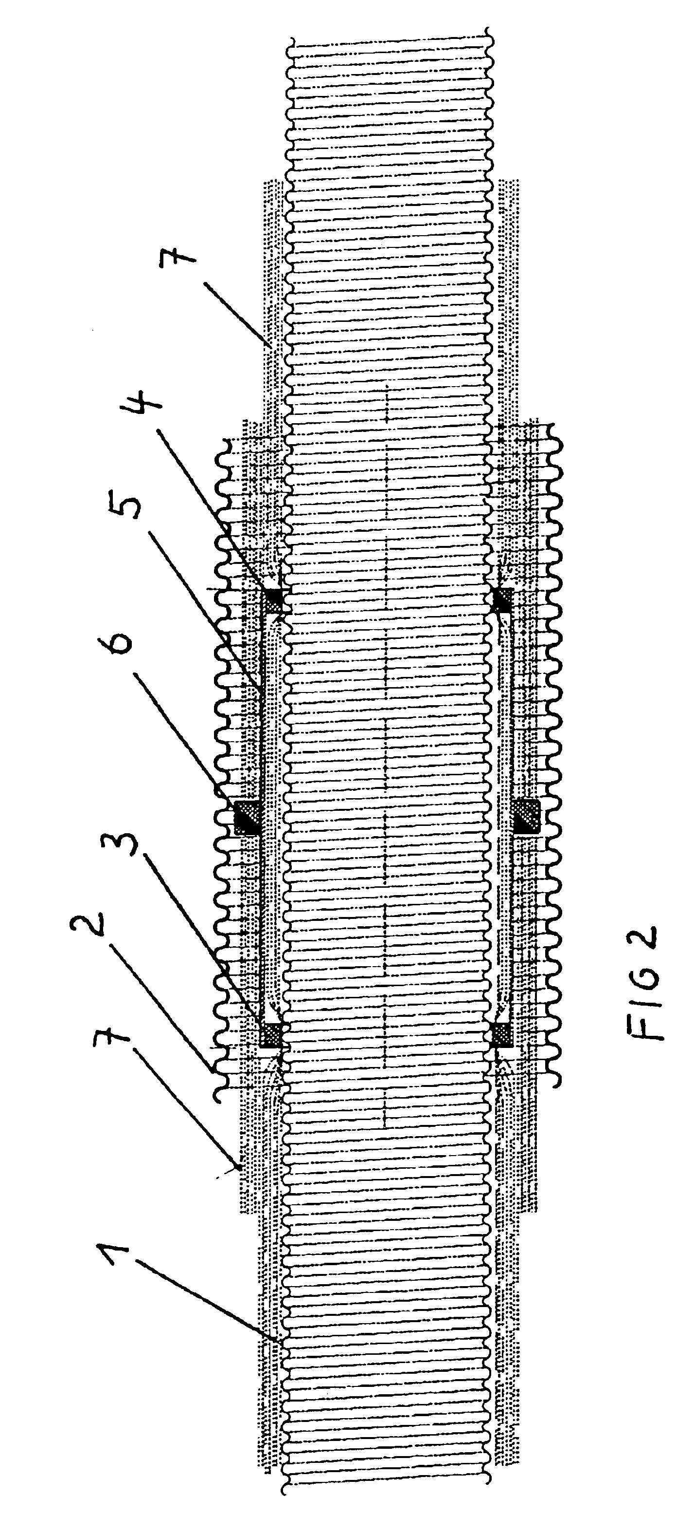
[0018]FIG. 1 shows a tube system comprising two conduits arranged concentrically to each other. The tube system is intended, for example, for transporting cryogenic media.

[0019]The tube system includes a corrugated interior metal tube 1, which is preferably made of stainless steel, and a likewise corrugated exterior metal tube 2, which is preferably also made of stainless steel. Because of the corrugation of the interior tube 1 and the exterior tube 2, the tube system is flexible and can be wound onto transport reels and thus can be transported to the place of use. If the tubes 1 and 2 are produced by shaping a nearly endless metal strip into a tube with a longitudinal slit, welding the longitudinal slit and subsequently corrugating the tube, it is possible to obtain tubes of nearly endless lengths.

[0020]Between the interior tube 1 and the exterior tube 2, spacers are provided at specific intervals in the longitudinal axial direction. These spacers comprise rings 3 and 4 seated on t...


PUM


Abstract

A spacer for a long substrate in the interior of a long tube, with a superinsulation material being disposed between the substrate and the tube. The spacer includes two rings (3, 4) seated on the substrate (1) and spaced apart from each other at a longitudinal axial distance, a tube section (5) supported on the rings (3, 4) and a second ring (6) disposed on the tube section (5). The first rings (3, 4), the tube section (5) and the second ring (6) are made of a material with poor thermal conductivity and high mechanical strength.

Description

[0001]This application is based on and claims the benefit of German Patent Application No. 103 10 960.9 filed Mar. 13, 2003.BACKGROUND OF THE INVENTION[0002]The invention relates to a spacer for a long substrate in the interior of a long tube, of the type wherein a superinsulation material is arranged between the substrate and the tube, and to a coaxial tube system with such a spacer.[0003]The invention is based on the following considerations:[0004]Optimal thermal insulation in refrigeration technology is achieved by multi-layer foil insulation in a high vacuum (superinsulation). The total heat flow is brought to what is currently the lowest technically possible value by minimizing the components Qgas, QFK and Qrad.[0005]The heat loss flows Qgas are reduced by evacuating the insulation space.[0006]The solid heat bridges, e.g., spacers, which are responsible for QFK, are structurally reduced by minimizing the solid-state contact flows.[0007]The radiation losses Qrad are reduced by m...

Claims


Application Information

Patent Timeline
Patent Type & Authority Patents(United States)
IPC IPC(8): F16L59/06F16L59/065F16L59/00F16L59/12F16L59/14
CPCF16L59/065F16L59/141F16L59/12
Inventor SCHIPPL, KLAUS
Owner NEXANS
Why Eureka
Try Eureka