Bidirectional pneumatic impact wrench

a pneumatic motor and impact wrench technology, applied in the field of pneumatic impact wrenches, can solve the problems of raising manufacturing costs, the air control valve cannot directly reverse the rotation of the pneumatic motor, etc., and achieve the effect of efficiently directing compressed air and simple structur

Inactive Publication Date: 2005-04-26
HUANG YUNG CHAO
View PDF8 Cites 71 Cited by
  • Summary
  • Abstract
  • Description
  • Claims
  • Application Information

AI Technical Summary

Benefits of technology

[0008]The main objective of the invention is to provide a pneumatic impact wrench that has a rotatable air control that has a simple structure and efficiently directs compressed air to a desired path in the pneumatic impact wrench.

Problems solved by technology

However, this kind of air control valve cannot directly reverse the rotation of the pneumatic motor and needs a reversing device to make the rotation of the motor reverse.
The conventional air control valve has a complicated structure and only makes the pneumatic motor rotate in one direction, which raises manufacturing cost.

Method used


Image

  • Bidirectional pneumatic impact wrench
  • Bidirectional pneumatic impact wrench
  • Bidirectional pneumatic impact wrench

Examples


Embodiment Construction

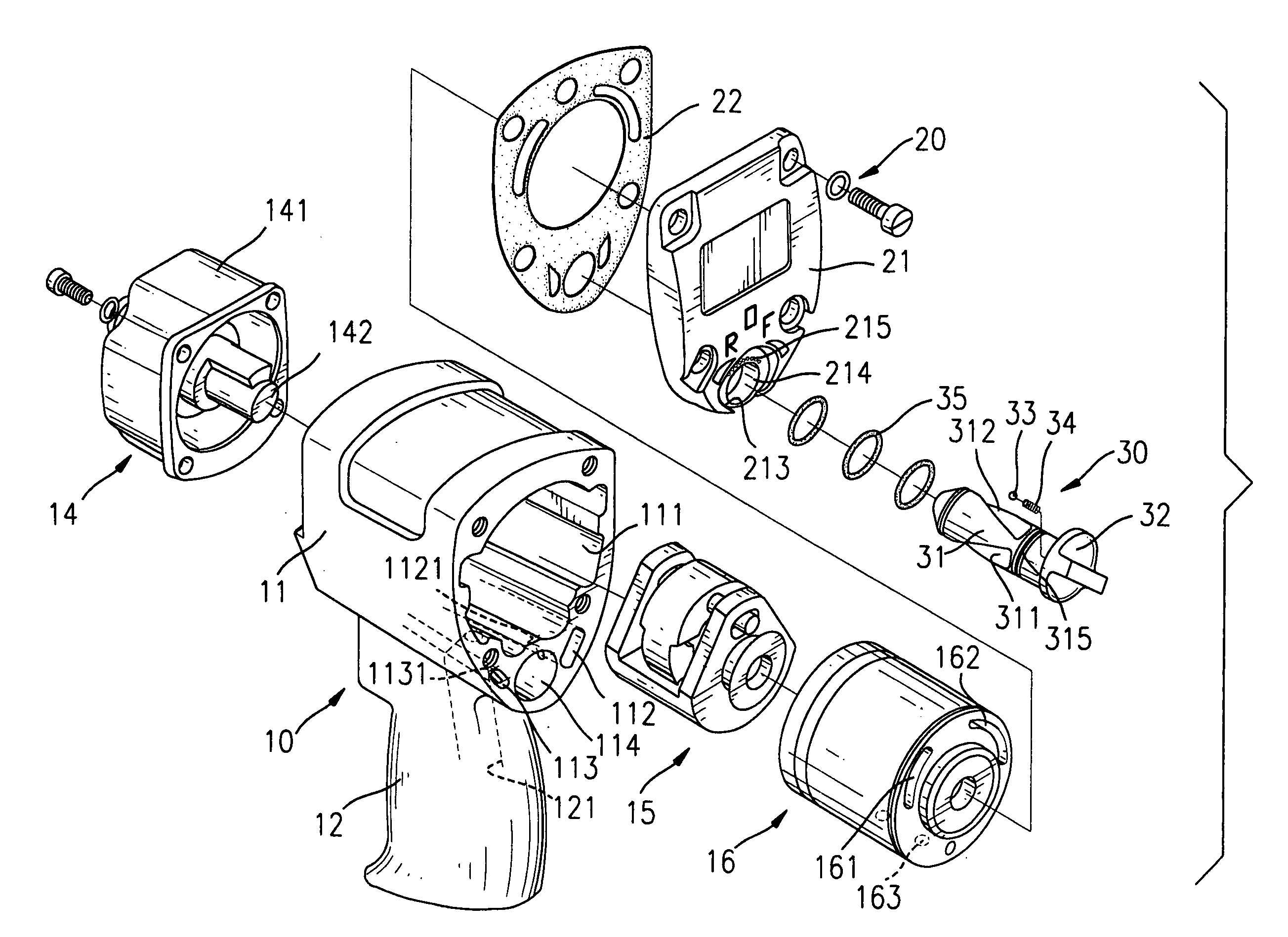
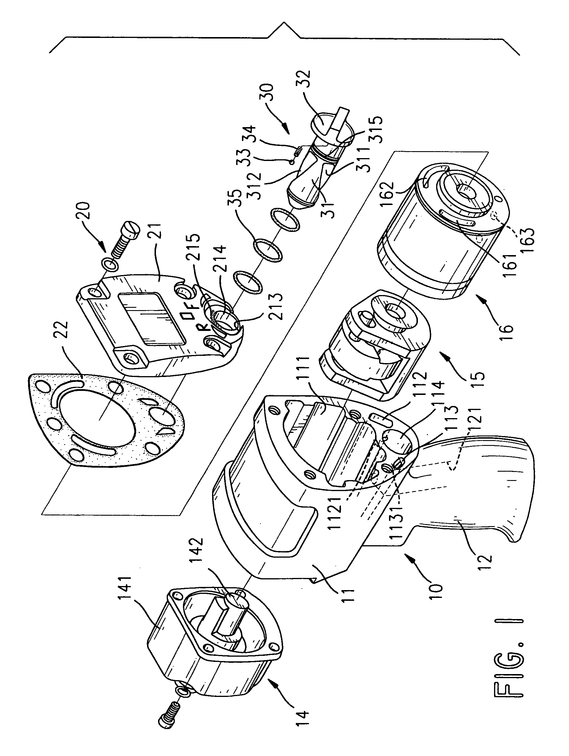
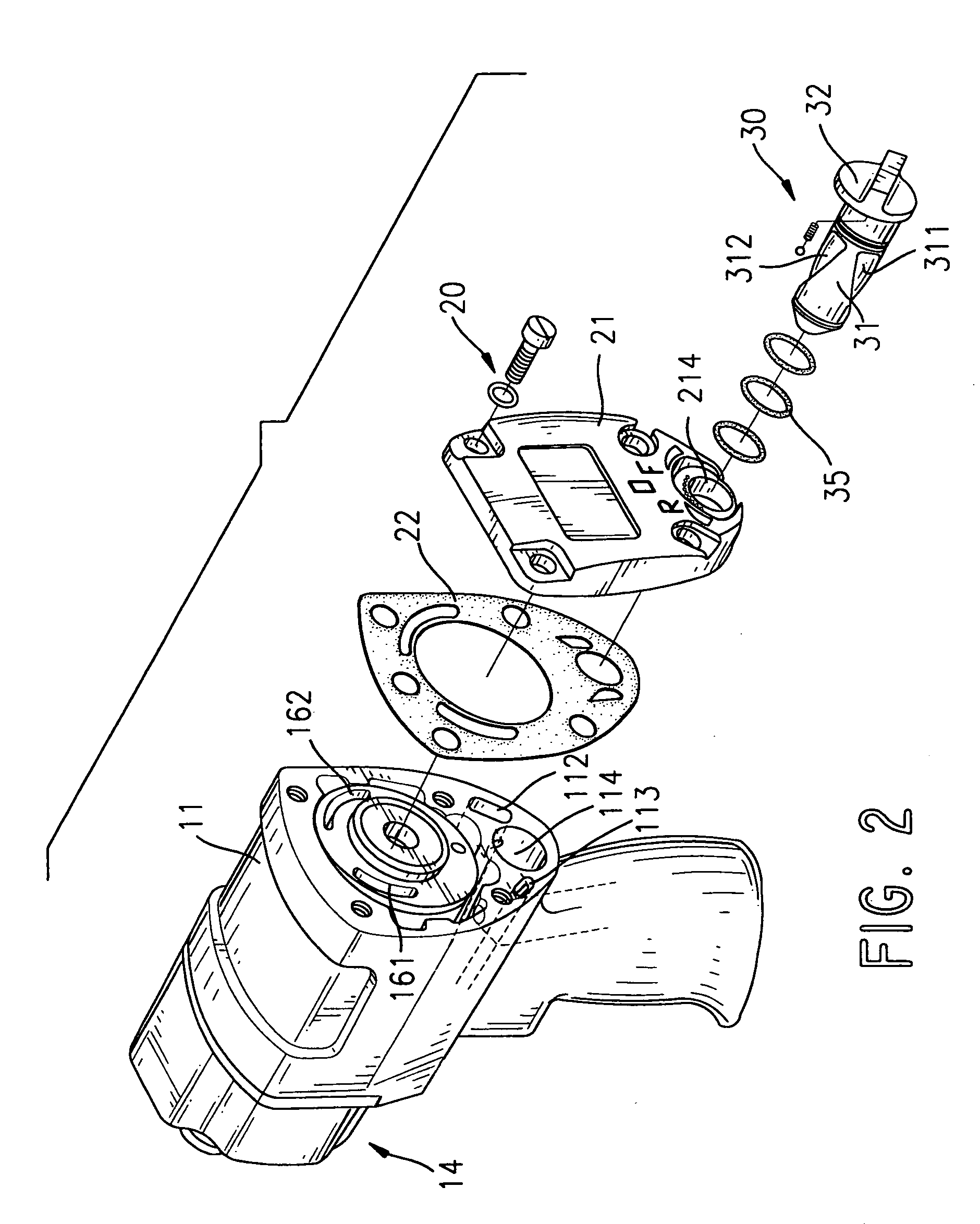
[0019]With reference to FIG. 1, a pneumatic impact wrench (not numbered) in accordance with the present invention comprises a housing (10), a front assembly (14), a hammer assembly (15), a pneumatic motor (16), a rear assembly (20) and an air control valve (30).

[0020]With further reference to FIG. 6, the housing (10) comprises a motor casing (11) and a handle (12). The motor casing (11) has a front (not numbered), a rear (not numbered), a bottom (not numbered), a motor chamber (111), a forward air passage (112), a reverse air passage (113), a valve chamber (114) and a motor-air discharge port (not numbered). The motor chamber (111) is defined longitudinally completely through the motor casing (11). The valve chamber (114) is defined in the rear of the motor casing (11) under the motor chamber (111). The forward and the reverse air passages (112, 113) are symmetrical and are defined in the motor casing (11) at the rear on opposite sides of the valve chamber (114) below the motor cha...


PUM

PropertyMeasurementUnit
diametersaaaaaaaaaa
diameteraaaaaaaaaa
rotationaaaaaaaaaa

Abstract

A bidirectional pneumatic impact wrench has a pneumatic motor and an air control valve. The pneumatic motor has a forward air inlet and a reverse air inlet. The air control valve directs compressed air selectively into either the forward air inlet or the reverse air inlet to change the direction of rotation of the pneumatic motor and includes a rotatable shaft. The shaft has an exterior surface and a spiral forward air groove and reverse air groove that are symmetrically defined in the exterior surface to direct the compressed air efficiently. The air control valve is simple to fabricate and directs the compressed air efficiently into the pneumatic motor to improve power and efficiency of the pneumatic motor.

Description

BACKGROUND OF THE INVENTION[0001]1. Field of the Invention[0002]The present invention relates to a pneumatic impact wrench, and more particularly to a bidirectional pneumatic impact wrench with a rotatable air control valve that has two spiral air grooves to direct compressed air to control the direction of rotation of a pneumatic motor in the bidirectional pneumatic impact wrench.[0003]2. Description of Related Art[0004]Pneumatic or air-driven impact wrenches are extensively used to rapidly fasten or loosen bolts or nuts. Most pneumatic impact wrenches generally have an air control valve to direct compressed air and control the direction of rotation of a drive shaft of the pneumatic impact wrench to fasten or loose bolts or nuts.[0005]A rotatable air control valve is convenient to use because a person just needs to rotate the air control valve to change the direction of rotation of the drive shaft. A conventional air control valve in a bidirectional pneumatic impact wrench uses a c...

Claims


Application Information

Patent Timeline
Patent Type & Authority Patents(United States)
IPC IPC(8): B23B45/00B23B45/04B25B21/02
CPCB25B21/02
Inventor HUANG, YUNG-CHAO
Owner HUANG YUNG CHAO
Why Eureka
Try Eureka