Holder for use in semiconductor device manufacturing and bio-medical sample processing

a technology for semiconductor devices and holders, applied in the direction of instruments, transportation and packaging, tray containers, etc., can solve the problems of destroying the structure of many biological specimens, and destroying the usefulness of specimens

Inactive Publication Date: 2005-04-26
TOUSIMIS RES
View PDF5 Cites 1 Cited by
  • Summary
  • Abstract
  • Description
  • Claims
  • Application Information

AI Technical Summary

Benefits of technology

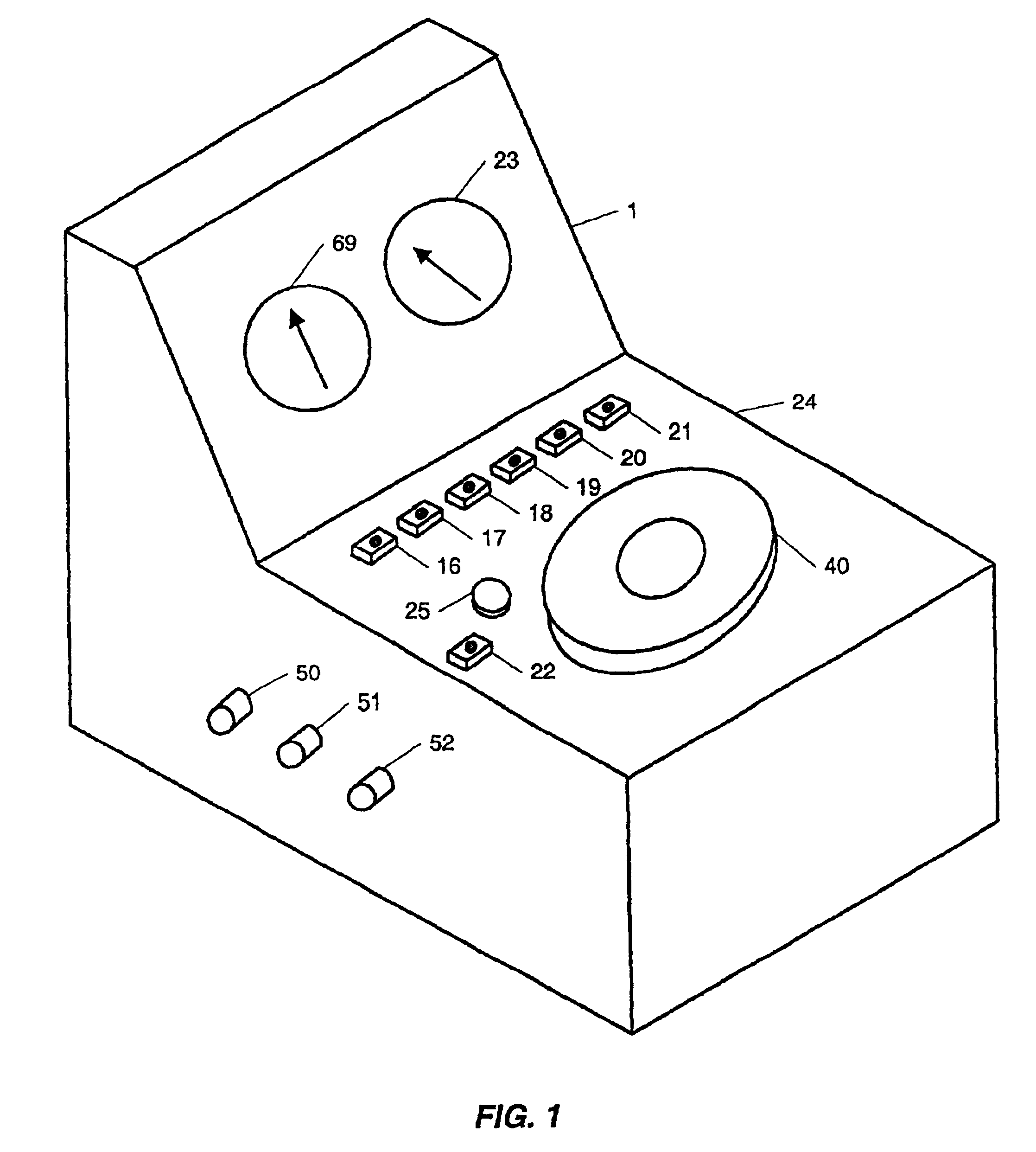
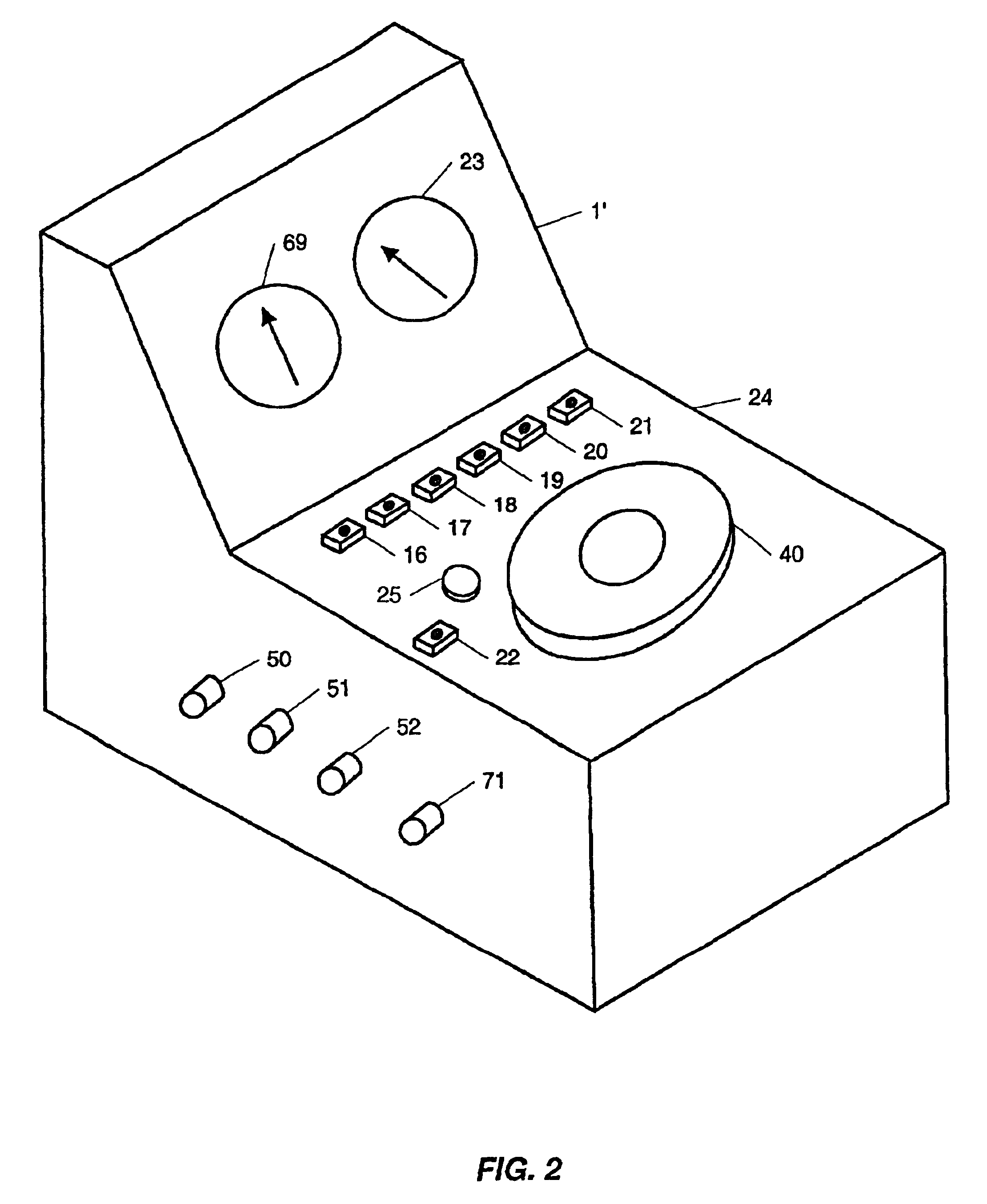
[0022]According to a fifth aspect of the invention, a critical point dryer apparatus comprising a drying chamber and a computer system wherein the computer system is adapted to controlling the drying chamber during a critical point drying process is provided. The computer system comprises a processor and a memory including software instructions adapted to enable the computer system. The software instructions enable the computer system to cool the drying chamber to a first chamber temperature. The software instructions further enable the computer system to fill the drying chamber with a transitional fluid having a critical point temperature and critical point pressure while maintaining the drying chamber at the first chamber temperature such that the transitional fluid completely displaces an intermediary fluid within a first time period. The software instructions further enable the computer system to activate at least one heater to raise the transitional fluid to its critical point pressure and critical point temperature, thereby reaching critical point equilibrium. The software instructions further enable the computer system to maintain the transitional fluid at the critical point equilibrium for a second time period. The software instructions further enable the computer system to bleeding the transitional fluid from the drying chamber while maintaining the drying chamber at the second chamber temperature and allowing the drying chamber pressure to drop.
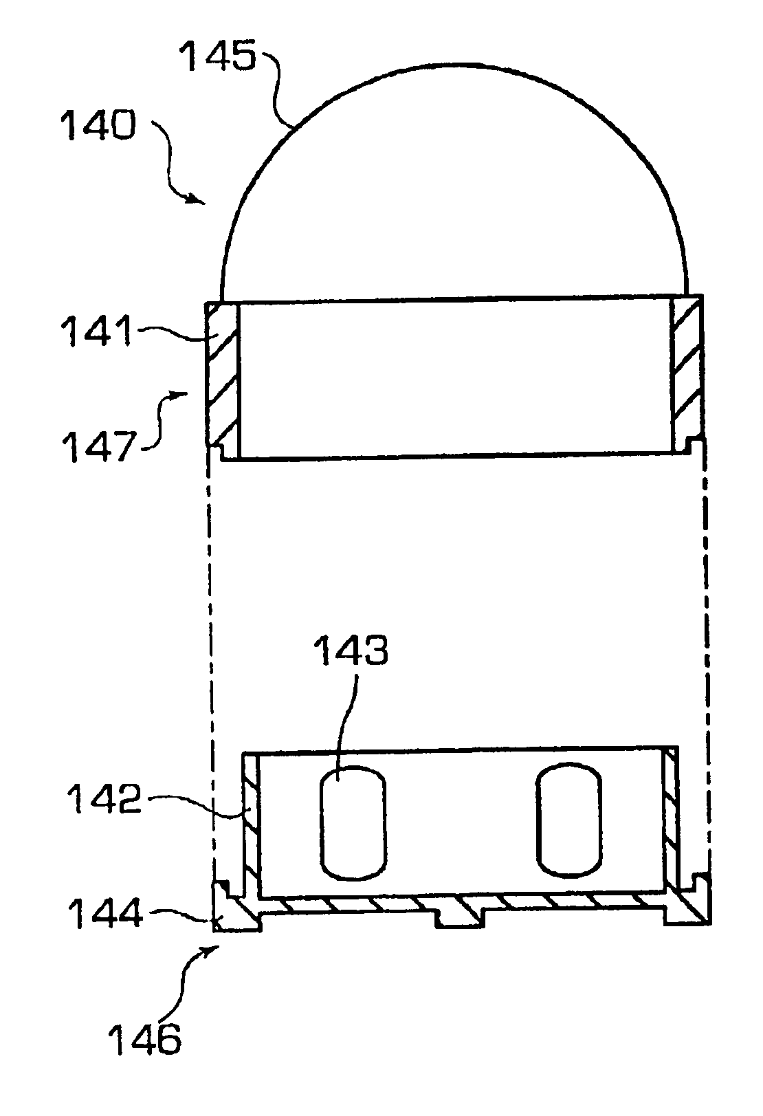
[0026]The holder has two positions corresponding to a position to allow fluid flow, and a position to provide fluid containment. When the holder is in a position to provide fluid containment, the outer section is placed over the inner base section, which allows the closing wall to close off the flow holes in such a way as to prevent any fluid contained within the inner base section to escape. The closing wall has only a slightly larger diameter than the retention wall, in order to provide a tight fit and allow the holder to be moved by an operator using the handle.
[0029]The holder has two positions corresponding to a position to allow fluid flow, and a position to allow fluid containment. When the holder is in a position to provide fluid containment, the outer retaining section is rotated around the inner holding section in such a way as to not allow the flow holes of each section to communicate with each other, and thus prevent fluid that is contained within the inner holding section to flow through the holes.
[0034]The holder has two positions corresponding to a position to allow fluid flow, and a position to provide fluid containment. When the holder is in a position to provide fluid containment, pressure is not applied to the plug actuating surface, which allows the plug seal to remain seated in the flow hole. When fluid flow is desired, pressure may be applied to the plug actuating surface by placing the holder into a position such that it is resting on an opposing surface which engages the plug actuating surface and causes the plug seal to move vertically upward, thereby unsealing the flow hole and allowing fluid to flow. The plug seal will return to a position that seals the flow hole when holder is removed from the opposing surface.

Problems solved by technology

While suitable for bacteria or other rigid structures, this method is detrimental to the structures of many biological specimens.
The surface tension forces, which turn a grape into a raisin during the drying process, cause sufficient distortion in the cell structure of many biological specimens thereby rendering them useless.
Additionally, unless the lengthy technique is followed precisely, structural damage from thermal expansion or ice crystal formation often results.
However, if the ethanol or acetone evaporates, surface tension forces would cause structural damage and destroy the specimen's usefulness.
These boundary forces often cause the destruction of the extremely delicate specimens when changing its internal liquid to a gas below the critical point.

Method used


Image

  • Holder for use in semiconductor device manufacturing and bio-medical sample processing
  • Holder for use in semiconductor device manufacturing and bio-medical sample processing
  • Holder for use in semiconductor device manufacturing and bio-medical sample processing

Examples


Embodiment Construction

[0067]Prior to describing the aspects of the present invention, some details concerning certain terms of art will be provided to facilitate the reader's understanding of the present invention and to set forth the meaning of various terms.

[0068]As used herein, the term “computer system” encompasses the widest possible meaning and includes, but is not limited to, microprocessors, standalone processors, networked processors, mainframe processors, and processors in a client / server relationship. The term “computer system” is to be understood to include at least a memory and a processor. In general, the memory will store, at one time or another, at least portions of executable program code, and the processor will execute one or more of the instructions included in that executable program code.

[0069]As used herein, the term “embedded computer system” includes, but is not limited to, an embedded central processor and memory bearing object code instructions. Examples of embedded computer sys...


PUM

PropertyMeasurementUnit
pressureaaaaaaaaaa
critical point temperatureaaaaaaaaaa
pressureaaaaaaaaaa

Abstract

Multipurpose holders for electronic components utilized during a fabrication process must allow the components to be submerged into baths of hydrofluoric acid, rinsed in de-ionized water (D.I.), placed into baths of alcohol for dehydration, and ultimately dried prior to further processing. The holders provide both fluid flow around the wafers while in each bath of fluid and while being processed by the critical point dryer, and a containment system to keep the wafer submerged in fluid at all times during the transfer between baths and the drying equipment.

Description

CROSS-REFERENCES TO RELATED APPLICATIONS[0001]This is a continuation-in-part of application Ser. No. 09 / 658,185 filed Sep. 8, 2000, now U.S. Pat. No. 6,493,964 the disclosure of which is incorporated herein by reference. Application Ser. No. 09 / 658,185 was filed under 35 U.S.C. § 111(a) claiming benefit pursuant to 35 U.S.C. § 119(e)(1) of the filing date of Provisional Application No. 60 / 206,726 filed on May 25, 2000 pursuant to 35 U.S.C. § 111(b).BACKGROUND OF THE PRESENT INVENTION[0002]1. Technical Field of the Present Invention[0003]This present invention relates to improvements in holders for sample preparation for electron microscopy and semiconductor wafer manufacturing. The present invention is embodied in a holder that holds semiconductor wafers in drying apparatuses and in liquid baths during the fabrication process of the wafers leading up to critical point drying, and alternatively provides fluid flow around the wafers or a containment system to keep the wafer submerged ...

Claims


Application Information

Patent Timeline
Patent Type & Authority Patents(United States)
IPC IPC(8): G01N1/40H01L21/00B65D6/12
CPCG01N1/40H01L21/67034G01N2001/4027
Inventor TOUSIMIS, ANASTASIOS J.TOUSIMIS, CHRISTOUSIMIS, YIANNI
Owner TOUSIMIS RES
Why Eureka
Try Eureka