
Thrust bearing

a technology of bearings and dividers, applied in the direction of bearings, roller bearings, shafts, etc., can solve the problems of reducing affecting the life of the bearing, and affecting the use of the drilling tools, so as to reduce the number of dividers, increase the capacity, and eliminate the effect of dividers

Inactive Publication Date: 2005-04-26
598992 SASKATCHEWAN
View PDF28 Cites 10 Cited by
  • Summary
  • Abstract
  • Description
  • Claims
  • Application Information

AI Technical Summary

Benefits of technology

[0008]What is required is a bearing that is capable of a longer useful life.
[0011]The key to obtaining maximum capacity in a thrust bearing lies in the number, length, and diameter of the rolling elements. Generally, as space in a cage is increasingly filled the rolling elements, the capacity increases. Therefore the cage design which allows for the most space to be occupied by the rolling elements will typically have the maximum capacity. The thrust bearing described above eliminates any dividers between the rollers and the design of the retainers allow for a rigid design that can use a minimum wall thickness.
[0012]The two retainers positively lock together to become a rigid cage. These factors enable a bearing to be designed for increased roller fill and maximum capacity. The invention increases the useful life of the drilling tool by extending the life of the thrust bearing. This is accomplished due to two inherent features of this invention. Firstly the two retainers with their locking mechanism form a sufficiently rigid cage with a minimum thickness occupied by said cage. Secondly the bearing does not have roller dividers as discussed above. This absence of dividers allows the lubricant to flush any abrasive particles out from between the rollers.
[0014]Even more beneficial results were obtained by creating a snap fit locking engagement between the first retainer and the second retainer. According to this aspect of the invention the first outer sidewall and the first inner sidewall of the first retainer have a first engagement profile. Similarly, the second outer sidewall and the second inner sidewall of the second retainer have a second engagement profile. The first engagement profile and the second engagement profile engage to secure the first retainer and the second retainer. Assembly is extremely rapid, which enables the thrust bearing to be manufactured in a cost effective manner. While this description describes an interlock on the inner and outer sidewalls it can be imagined that a similar gain could be achieved using the described locking method on either the inner or outer sidewall or both.
[0015]The Prototype was withdrawn for inspection after 85 hours. Upon inspection it showed no wear. It is believed that this performance can be attributed to two factors. The first factor, is the cage design allows for the maximum amount of space to be filled by rollers thereby increasing the capacity and correspondingly increasing the life. The second is that the elimination of the dividers enabled lubricants to more effectively wash away abrasive particles which tend to adversely affect the life of a bearing.

Problems solved by technology

The failure of tools used in oil and gas drilling, in the majority of cases, can be attributed to a failure of either seals or bearings.
Polymeric cages are not preferred for high temperature applications as many of the materials can easily degrade at high temperatures.
This can have a detrimental effect on the life of said bearing.
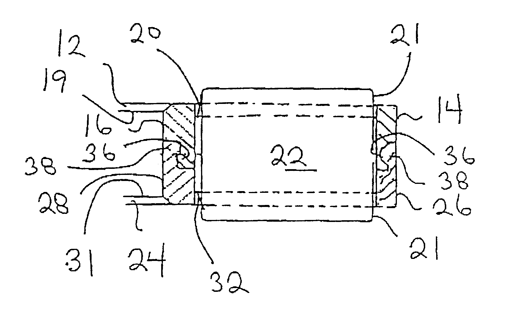
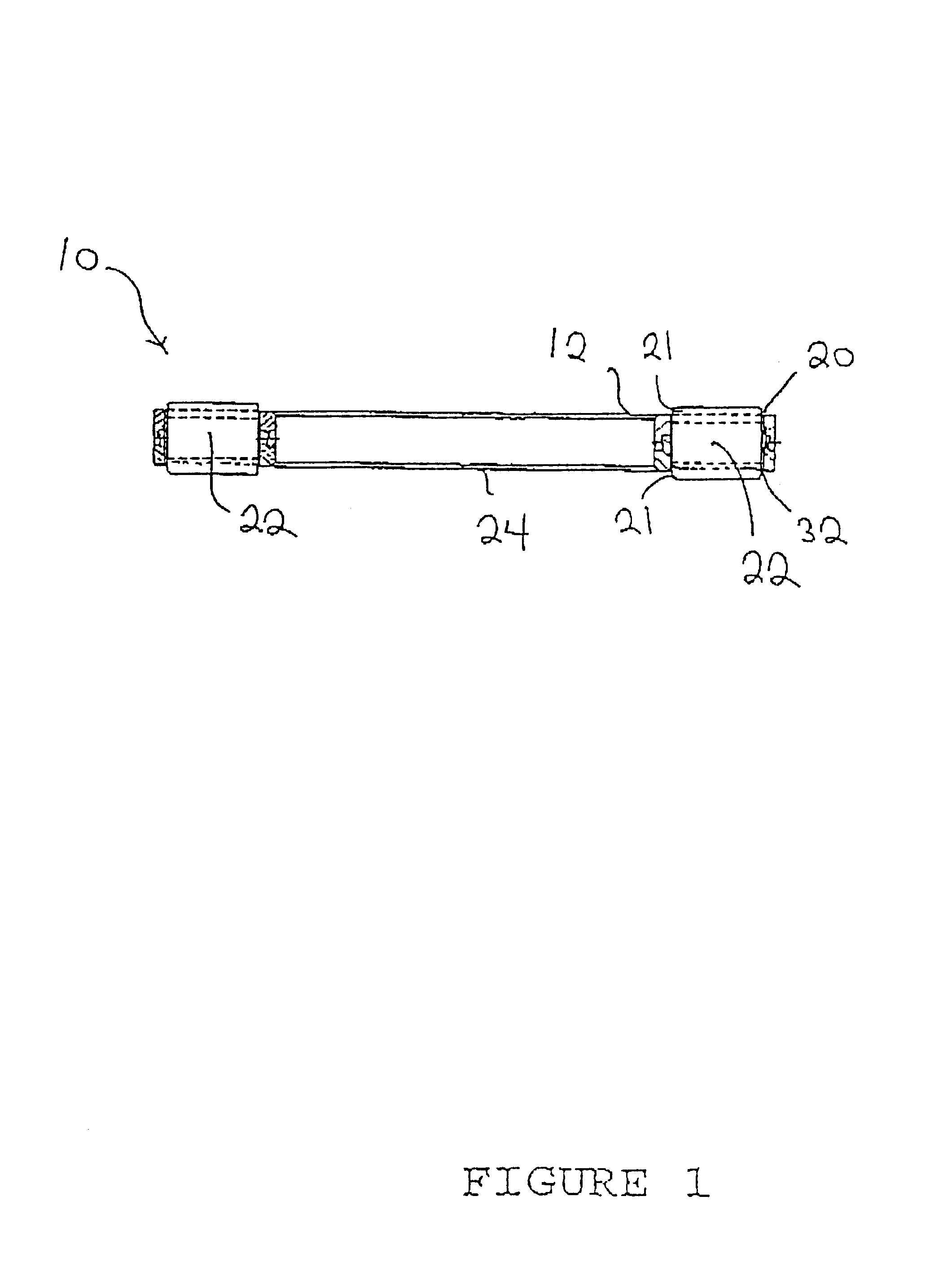
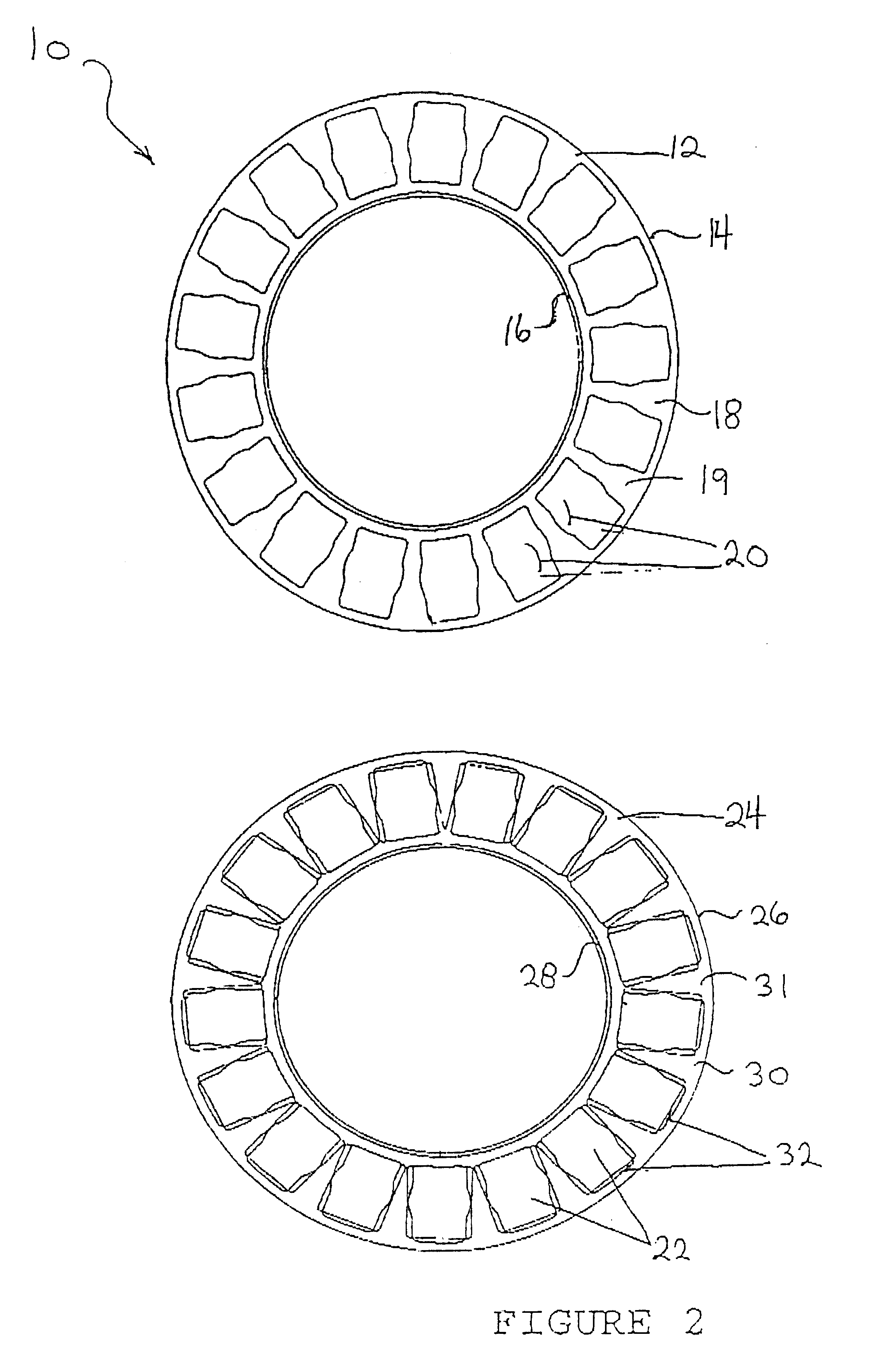
The lubricant has a limited ability to “wash” abrasive grit out from between the rollers.
Eventually, a build up of abrasive grit occurs and one or more of the rollers becomes jammed against the cage.

Method used


Image

  • Thrust bearing
  • Thrust bearing
  • Thrust bearing

Examples


Embodiment Construction

[0021]The preferred embodiment, a thrust bearing generally identified by reference numeral 10, will now be described with reference to FIGS. 1 through 4.

[0022]Referring to FIG. 2, there is a thrust bearing 10 that includes an annular first retainer 12 and an annular second retainer 24. First retainer 12 has a circular first outer sidewall 14 and a concentric circular first inner sidewall 16. There is a first web 18 that extends between first outer sidewall 14 and first inner sidewall 16. First web 18 has a planar interior surface 19 with a plurality of first openings 20. Referring to FIG. 1, each of first openings 20 is adapted to accommodate a radiused portion 21 of a roller 22. Referring to FIG. 2, annular second retainer 24 includes a circular second outer sidewall 26 and a concentric circular second inner sidewall 28. A second web 30 that extends between second outer sidewall 26 and second inner sidewall 28. Second web 30 has a second planar interior surface 31 with a plurality ...


PUM


Abstract

A thrust bearing includes an annular first retainer, an annular second retainer and a plurality of rollers. The first retainer and second retainer are secured together to form a bearing cage. Each retainer has a circular outer sidewall, a concentric circular inner sidewall, and a web that extends between the outer sidewall and the inner sidewall. The web has a planar interior surface with a plurality of openings each adapted to accommodate a radiused portion of one of the rollers. The use of a web with a planar interior surface, without dividers, provides two advantages. The design leaves a maximum amount of room for rollers in the bearing which increases the bearing's capacity. The assembled cage allows for better lubricant flow to lubricate the bearing and wash potentially abrasive particles away from the rollers.

Description

CROSS-REFERENCE TO RELATED APPLICATION[0001]This application is a continuation of prior U.S. application Ser. No. 09 / 741,773, filed Dec. 15, 2000, abandoned, priority from the filing date of which is hereby claimed under 35 U.S.C.§ 120.FIELD OF THE INVENTION[0002]The present invention relates to a thrust bearing and, in particular, a thrust bearing suitable for use in tools used for drilling oil and gas wells.BACKGROUND OF THE INVENTION[0003]The failure of tools used in oil and gas drilling, in the majority of cases, can be attributed to a failure of either seals or bearings. This patent application will address premature bearing failure.[0004]There are two types of thrust bearings currently used is oil and gas drilling applications; thrust bearings having polymer plastic cages and thrust bearings having metallic cages. Polymer plastic bearings have a cage formed by two retainers joined together by means of rivets or adhesives to form a cage. The cage has solid dividers or cross bar...

Claims


Application Information

Patent Timeline
Patent Type & Authority Patents(United States)
IPC IPC(8): F16C33/46F16C19/22F16C19/30
CPCF16C19/305F16C33/4641F16C2226/74F16C2352/00
Inventor HORLEY, WAYNE
Owner 598992 SASKATCHEWAN
Learn More