Water pump and method of closure

Inactive Publication Date: 2005-04-26
GM GLOBAL TECH OPERATIONS LLC
View PDF3 Cites 2 Cited by
  • Summary
  • Abstract
  • Description
  • Claims
  • Application Information

AI Technical Summary

Benefits of technology

[0006]Once the plug and housing are assembled, the adhesive is allowed to set, creating a seal that pre

Problems solved by technology

Machining of the housing and/or cover and assembly of the cover, sc

Method used


Image

  • Water pump and method of closure
  • Water pump and method of closure
  • Water pump and method of closure

Examples


Embodiment Construction

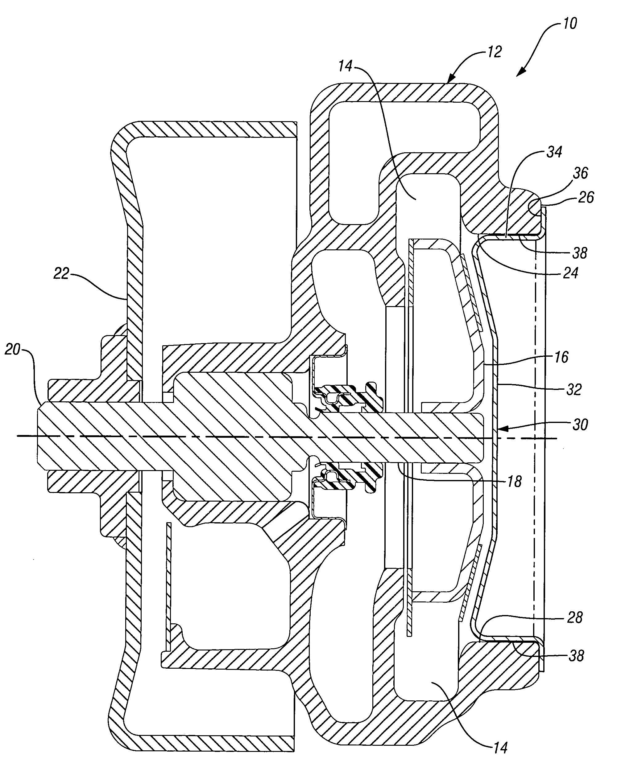
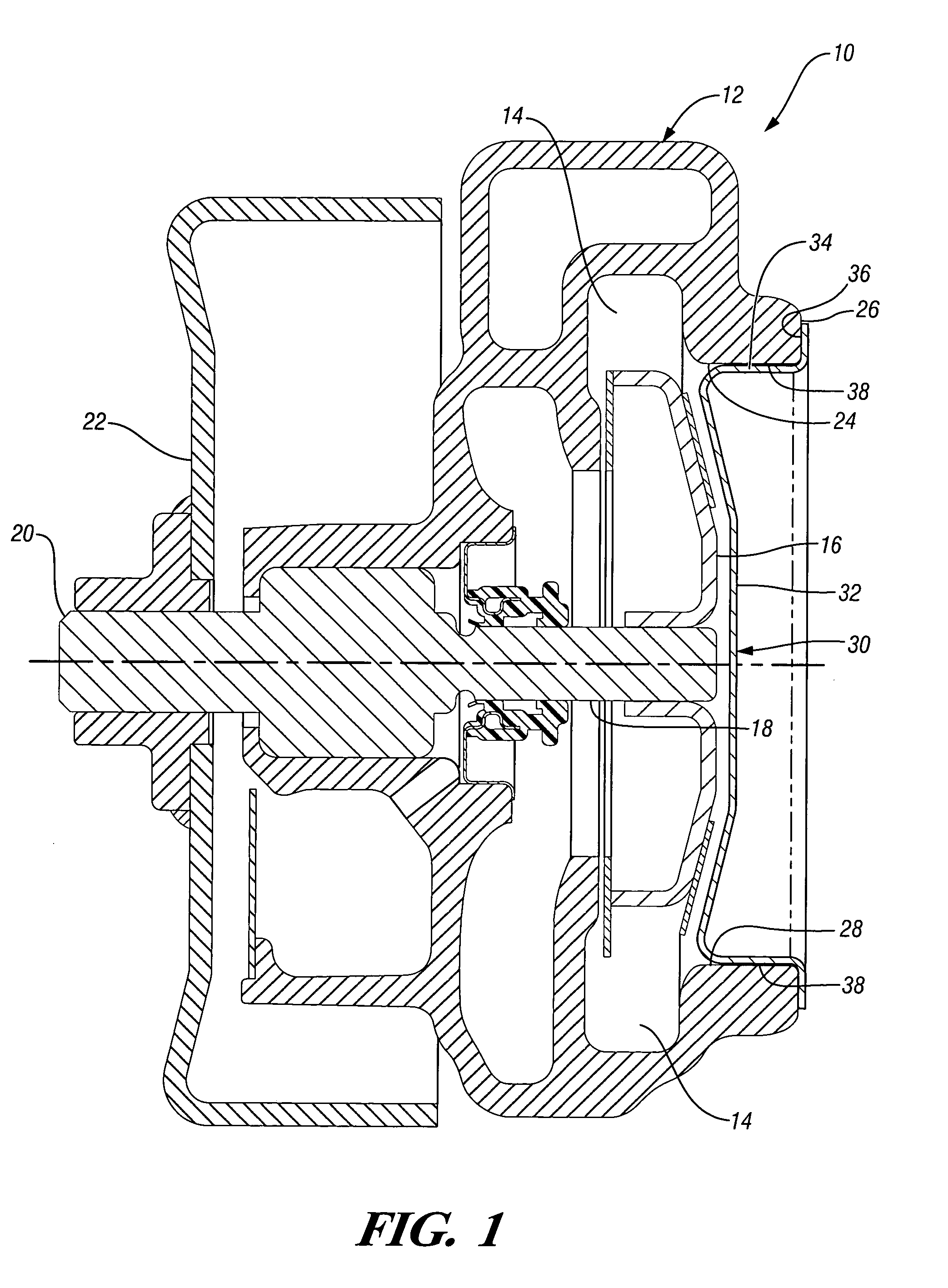
[0010]Referring now to FIG. 1 of the drawings in detail, numeral 10 generally indicates a water pump for an automotive engine. The water pump has a housing 12 internally defining a flow chamber 14 containing a rotatable impeller 16. The impeller 16 is fixed on a drive shaft 18 forming an assembly rotatable in the housing 12. An exterior portion 20 of the drive shaft 18 mounts a pulley 22 adapted to be driven by an accessory drive belt for pumping pressurized coolant through an engine cooling system.

[0011]For assembly purposes the housing 12 has an impeller assembly opening 24 adjacent the impeller 16. The opening 24 is defined by a radial outer surface 26 and a continuous axial inner retention surface 28.

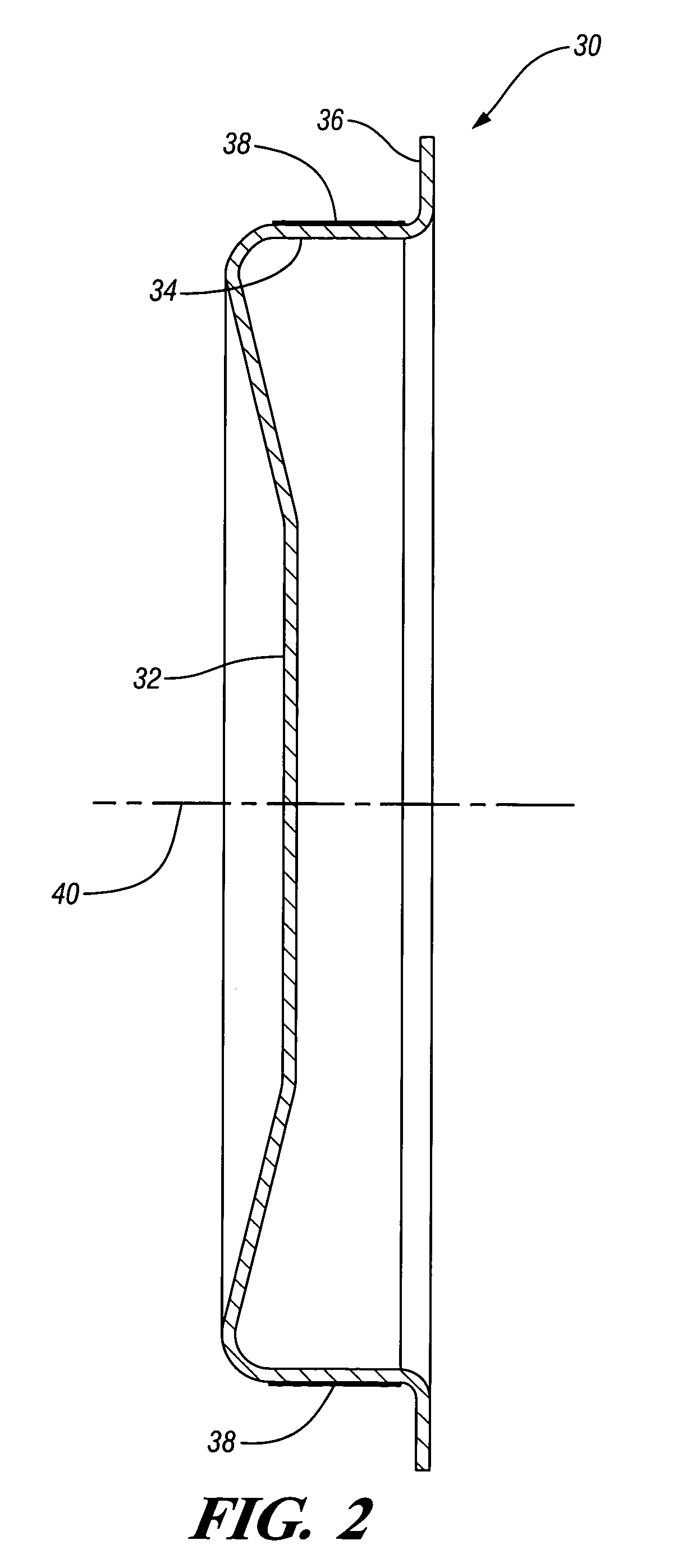
[0012]The opening 24 is closed by a disk shaped plug 30 shown in FIG. 2 and configured to fit in the assembly opening 24 of the housing 12. The plug 30 is formed of sheet metal and includes a radial closure portion 32 surrounded by a continuous axial flange 34 connected outwardly w...


PUM

PropertyMeasurementUnit
Forceaaaaaaaaaa
Surfaceaaaaaaaaaa

Abstract

A water pump having a housing with an opening defined by an axial inner retention surface and a radial outer surface. A plug formed of sheet metal includes a radial closure portion surrounded by a continuous axial flange adapted to be press fitted into the inner retention surface of the housing. Before assembly, an adhesive is applied to either the axial flange of the plug or the inner retention surface of the housing. The plug is then pressed into the housing so that the flange of the plug engages the inner retention surface of the housing. After the adhesive sets, a water tight seal is formed between the plug and the housing adequate to hold pressurized coolant within the housing of the water pump.

Description

TECHNICAL FIELD[0001]This invention relates to automotive engine water pumps and, more particularly, to methods of closing an impeller assembly opening.BACKGROUND OF THE INVENTION[0002]An automotive engine water pump is commonly provided with a housing having an assembly opening for inserting an impeller assembly into the housing. A cover is provided to close the opening and may be secured by screws and sealed by an o-ring seated in a groove of the housing or cover to prevent leakage of the engine coolant. Machining of the housing and / or cover and assembly of the cover, screws and o-ring to the housing adds complexity and cost to the pump.[0003]A simplified automotive water pump assembly not requiring O-rings or machined grooves is desired to reduce assembly time, complexity, and costs.SUMMARY OF THE INVENTION[0004]The present invention provides a simplified water pump. The pump having a housing with an assembly opening for installation of an impeller assembly. The opening is define...

Claims


Application Information

Patent Timeline
IPC IPC(8): F04D29/60F04D29/42F04D29/62
CPCF04D29/426F04D29/4266F04D29/628Y10S29/001Y10T29/49885Y10T29/49243Y10T29/49982Y10T29/49945Y10T29/49238Y10T29/49906
Inventor MESSIH, NADER A.IONESCU, ERNEST C.
Owner GM GLOBAL TECH OPERATIONS LLC
Why Eureka
Try Eureka