Thrombolysis catheter system with fixed length infusion zone

a catheter system and infusion zone technology, applied in the field of catheter systems, can solve problems such as complicated device construction and operation, and achieve the effect of maximizing the options of patients

Inactive Publication Date: 2005-04-26
LAKE REGION MFG
View PDF26 Cites 14 Cited by
  • Summary
  • Abstract
  • Description
  • Claims
  • Application Information

AI Technical Summary

Benefits of technology

[0018]In a preferred practice of the above method, a radiopaque structure on the catheter, usually on its distal segment, is monitored while the catheter is positioned within the vasculature. A plurality of radiopaque structures, such as platinum rings or bands, may be disposed along the length of the catheter, and on the steerable guidewire and on the occluder wire. These structures appear more intense than adjacent, non-radiopaque materials under fluoroscopic examination. Generally, a steerable guidewire will have a radiopaque distal tip and possibly additional proximally-located radiopaque structures. By observation of these radiopaque structures, the progress of the catheter into the vasculature can be observed, the location of the balloon or balloons (and therefore the infusion zone) relative to the treatment site can be determined, and the relationship between the catheter and the guidewire or occluder wire can be monitored. Utilization of the cooperatively located radiopaque structures in catheter placement and in therapeutic application is a particularly advantageous aspect of the present methods.
[0019]Yet a further aspect of this invention comprises a kit. A kit of this invention comprises an occluder means such as a tip occluder wire having an enlargement adjacent its distal end and a steerable guidewire. The guidewire preferably has an enlargement adjacent its distal end, thereby incorporating the features of both a steerable guidewire and a non-steerable occluder wire. The diameter of the enlargement of either or both of the guidewire or occluder wire is determined by the interior diameter of the reduced diameter segment of the primary lumen of the catheter. A kit having at least the above three components offers medical personnel employing a catheter of this invention the ability to maximize their options with respect to patient treatment. Kit components may include other necessary or desirable equipment such as stopcocks, syringes and gloves.

Problems solved by technology

The Daniels et al. design, however, requires the use of the interlumenal space as a fluid passageway, thereby complicating the construction and operation of the device.

Method used


Image

  • Thrombolysis catheter system with fixed length infusion zone
  • Thrombolysis catheter system with fixed length infusion zone
  • Thrombolysis catheter system with fixed length infusion zone

Examples


Embodiment Construction

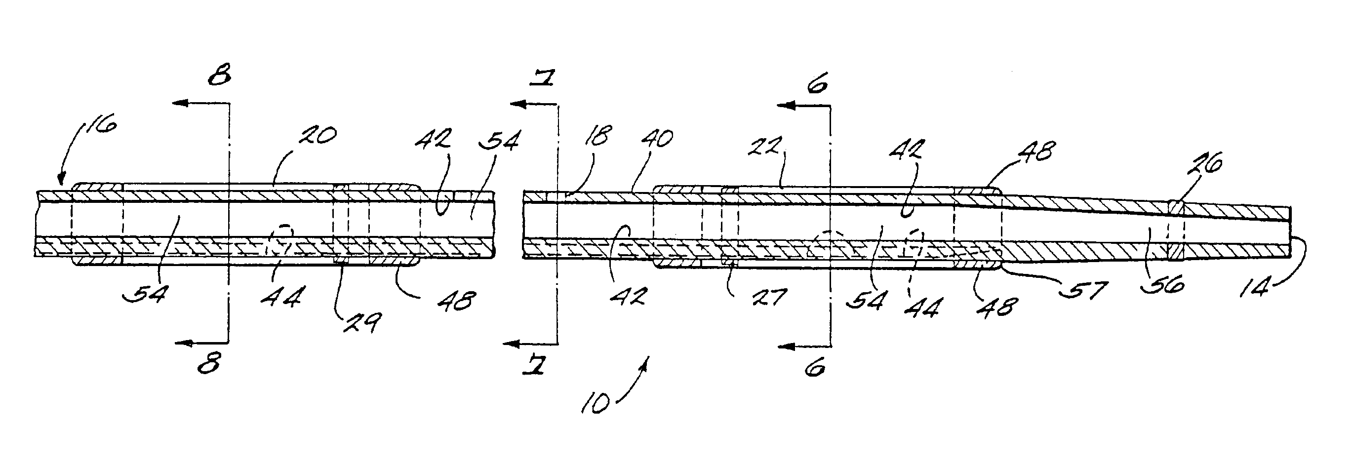
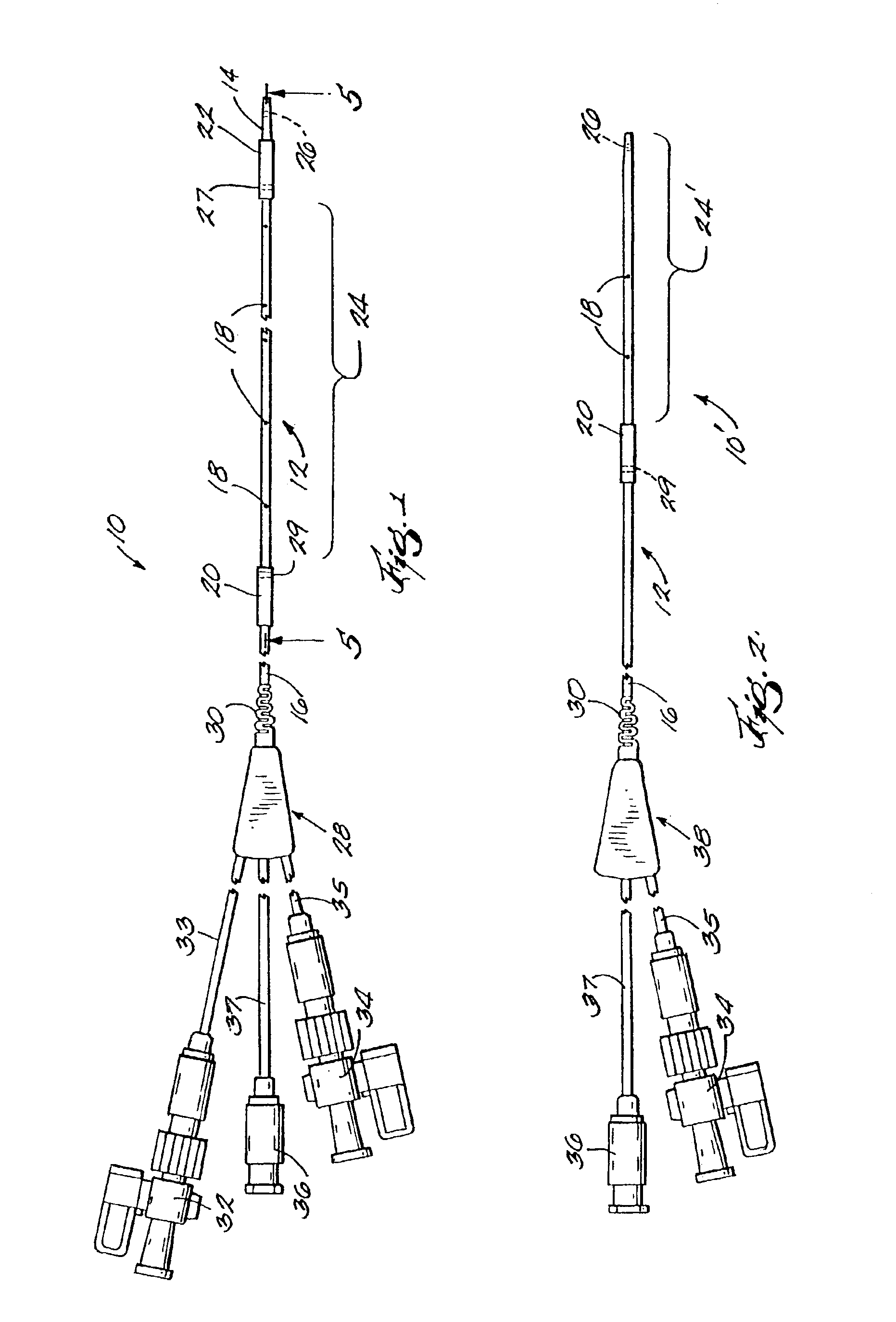
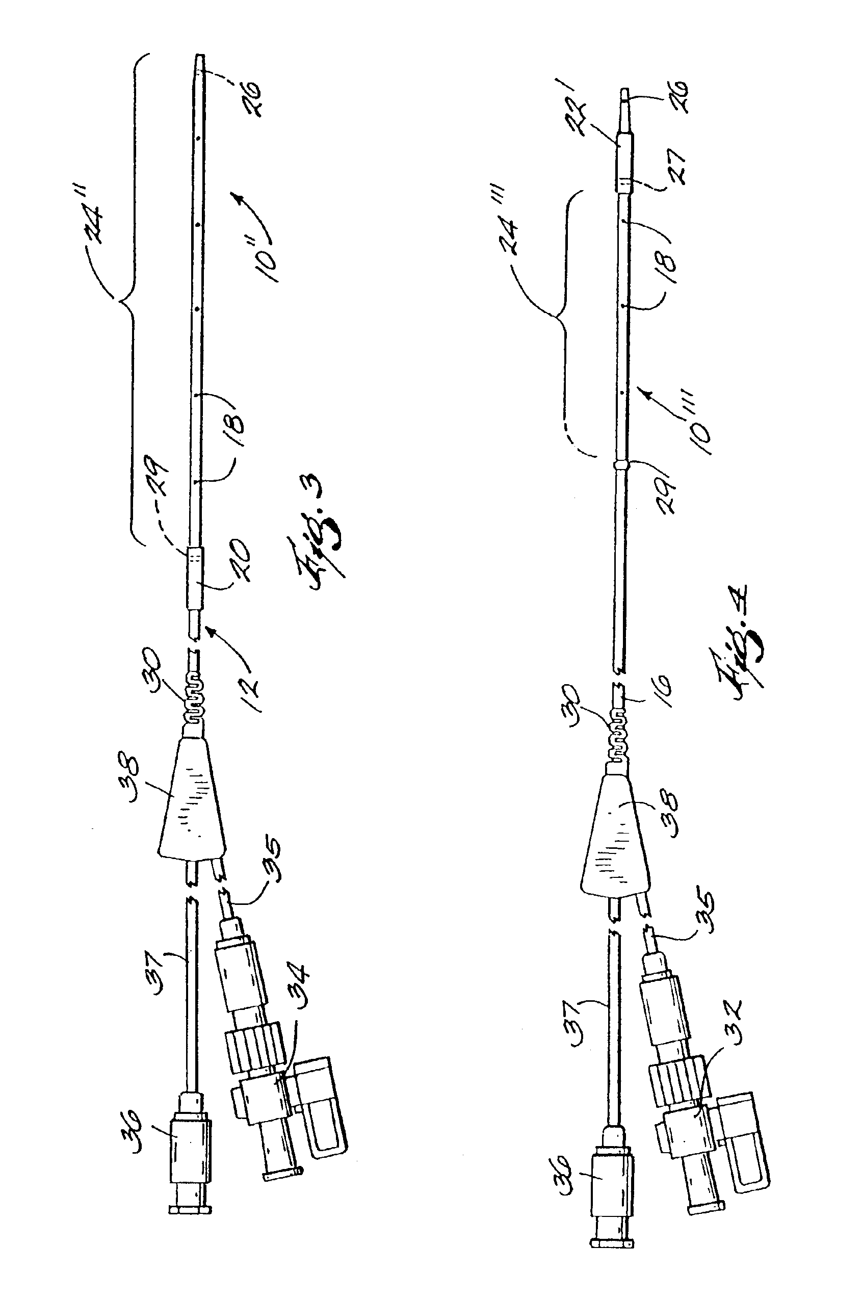
[0034]FIG. 1 is a plan view of a thrombolysis catheter or catheter system 10 of the present invention. Catheter 10 comprises a cylindrical catheter body 12. Catheter body 12 is flexible so as to be able to negotiate tortuous vascular structures and has distal and proximal ends 14, 16 respectively. For purposes of reference herein, the terms “distal” and “proximal” are determined from the frame of reference of a user. Thus a “proximal” structure or indication tends to be located closer to the user. Catheter body 12 has therein (and defines) a plurality of radial orifices 18. Catheter body 12 also has located on its external surface proximal and distal balloons 20, 22, respectively. Balloons 20, 22 are shown in their deflated state, i.e., substantially as they would appear as the catheter is being deployed within a patient's vasculature.

[0035]Between balloons 20, 22 is an infusion zone or operating segment 24. Infusion zone 24 is the working or operating portion of the catheter system...


PUM


Abstract

A thrombolysis catheter system having a fixed length infusion zone is disclosed. The invention contemplates apparatus, method and kit aspects. The apparatus, which has the capability to track a guidewire, uses a multilumen catheter to deliver radially thrombolytic agent to an infusion zone defined by one or more balloon means. In one aspect, with an occluder means, a primary lumen of the catheter is used both for catheter placement and delivery of fluid. The method discloses utilization of radiopaque indicia to place the catheter in proximity to the occlusion or diseased tissue to be treated. The kit includes a catheter of the invention in conjunction with a steerable guidewire and a tip occluder wire, either or both of the tip occluder wire and the guidewire having an enlargement on their distal tip which cooperates with a reduced diameter portion of the catheter lumen.

Description

CROSS-REFERENCE TO RELATED APPLICATIONS[0001]This application is a continuation of U.S. application Ser. No. 09 / 643,794, filed Aug. 22, 2000 now U.S. Pat. No. 6,488,672, which is a continuation of U.S. application Ser. No. 08 / 101,989, filed Aug. 4, 1993, now U.S. Pat. No. 6,113,576, issued Sep. 5, 2000.BACKGROUND OF THE INVENTION[0002]1. Field of the Invention[0003]This invention relates generally to devices used to clear obstructions in body passageways, more particularly, this invention relates to apparatuses and methods of treating such obstructions by the infusion of chemical thrombolytic agents. Yet more particularly, this invention relates to catheters and to catheter systems for exposing vascular obstructions to therapeutic agents, generally to effectuate their removal.[0004]2. Description of the Prior Art[0005]The use of catheter systems to treat various medical conditions has been known for some time. In treating a particular area within a body passageway, it is often desir...

Claims


Application Information

Patent Timeline
Patent Type & Authority Patents(United States)
IPC IPC(8): A61M25/10A61M25/00A61F2/958
CPCA61M25/003A61M25/1011A61M25/0028A61M2025/1052A61M2025/0079A61M2025/0098A61M2025/004
Inventor DANCE, CREG W.OLSON, STEVEN L.
Owner LAKE REGION MFG
Why Eureka
Try Eureka