Method and apparatus for uniform heating in a microwave oven

a microwave oven and uniform heating technology, applied in the field of microwave ovens, can solve the problems of undesirably high energy density and low energy density of places, and achieve the effect of uniform heating of loads and eliminating the formation of hot and cold spots

Inactive Publication Date: 2005-04-26
WHIRLPOOL CORP
View PDF7 Cites 108 Cited by
  • Summary
  • Abstract
  • Description
  • Claims
  • Application Information

AI Technical Summary

Benefits of technology

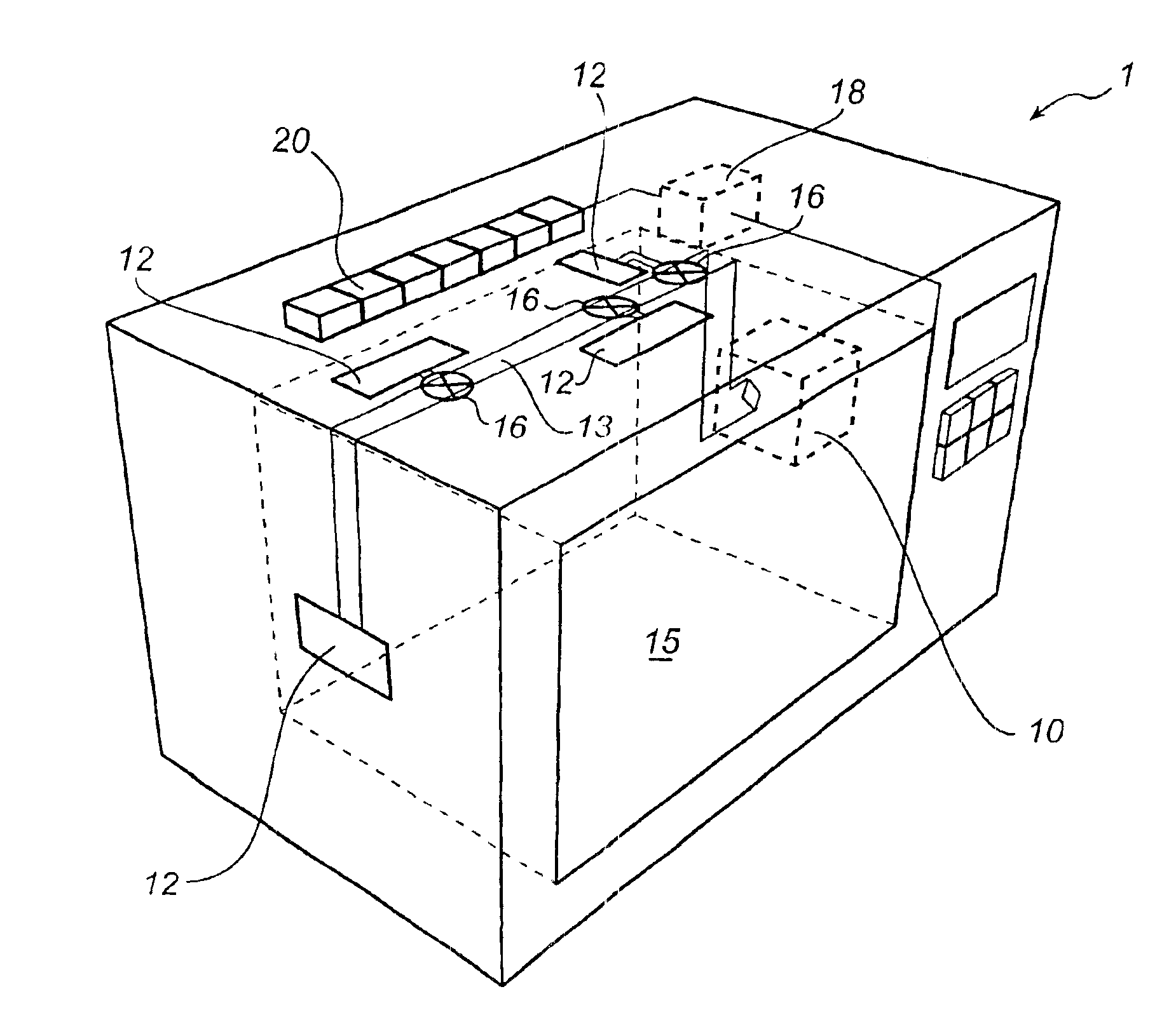
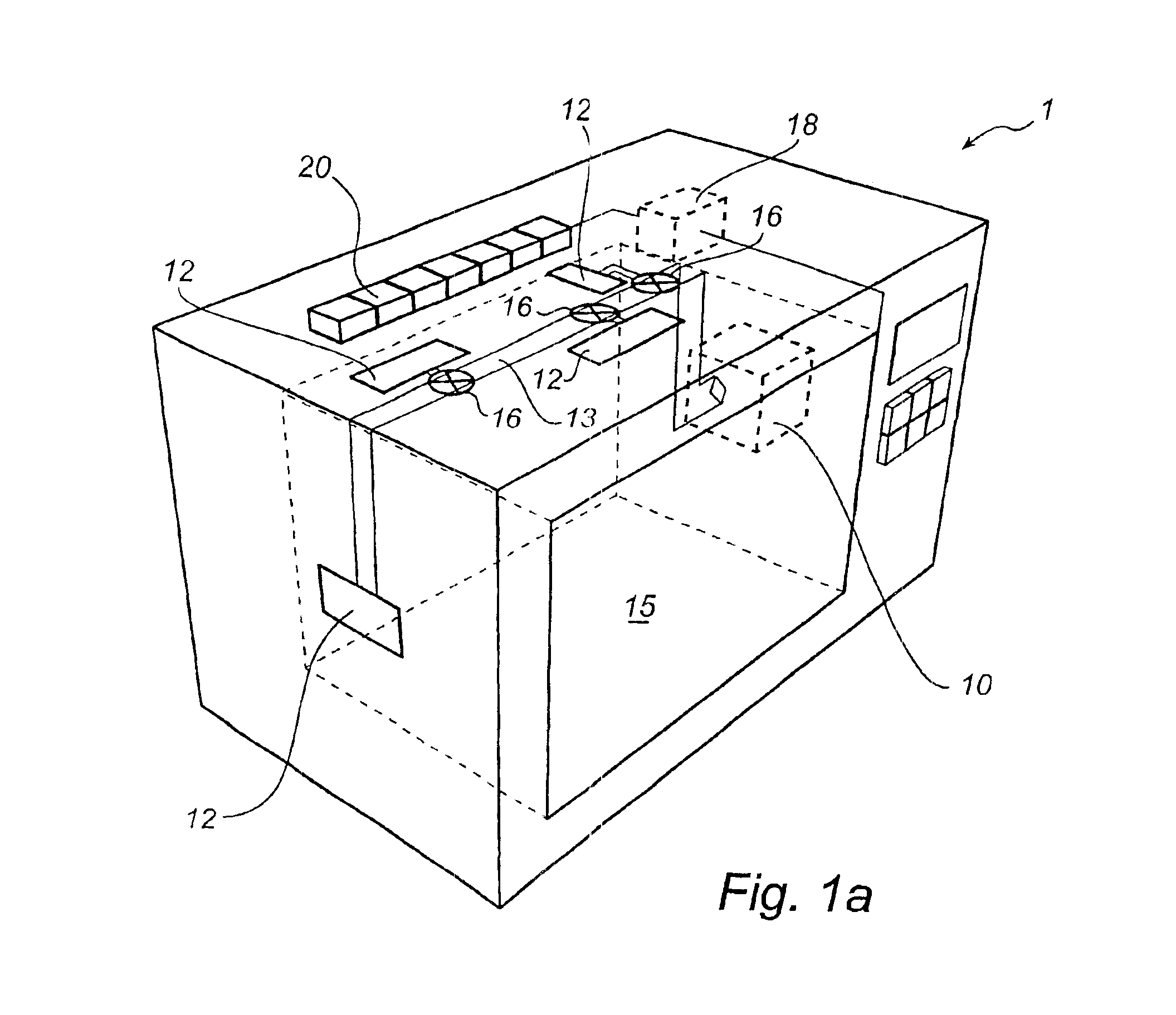
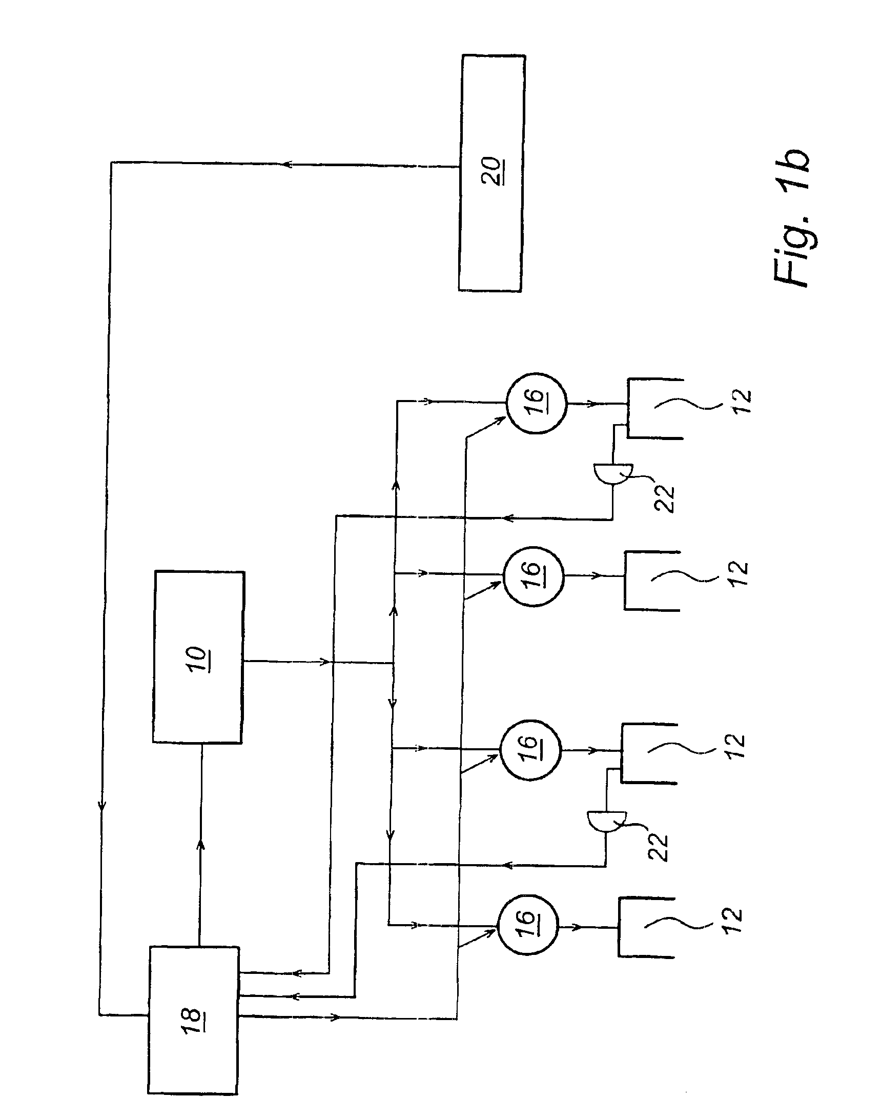
[0021]A great advantage of the present invention is thus that a substantially more uniform heating of a load placed in the cavity of a microwave oven is provided. Unlike prior-art technique, it is possible by means of the present invention to eliminate the formation of hot and cold spots in the cavity to a very large extent. This uniform heating is allowed by the fact that the mode pattern in the cavity is controlled by means of microwave feeding via carefully positioned feeding ports. At least one feeding port then has the property that only one predetermined mode in the cavity can be fed from said feeding port. Consequently, an uncontrolled energy distribution in the cavity is efficiently avoided.
is thus that a substantially more uniform heating of a load placed in the cavity of a microwave oven is provided. Unlike prior-art technique, it is possible by means of the present invention to eliminate the formation of hot and cold spots in the cavity to a very large extent. This uniform heating is allowed by the fact that the mode pattern in the cavity is controlled by means of microwave feeding via carefully positioned feeding ports. At least one feeding port then has the property that only one predetermined mode in the cavity can be fed from said feeding port. Consequently, an uncontrolled energy distribution in the cavity is efficiently avoided.

Problems solved by technology

However, interference between the modes in the cavity results in places with undesirably-low energy density and places with undesirably high energy density.
Such places ate sometimes called “cold spots” and “hot spots”, respectively, since the heating of the load in these places becomes too low and too high, respectively.

Method used


Image

  • Method and apparatus for uniform heating in a microwave oven
  • Method and apparatus for uniform heating in a microwave oven
  • Method and apparatus for uniform heating in a microwave oven

Examples


first embodiment

[0070]FIG. 16 shows a feeding port according to the present invention. In the shown example microwaves are led to the feeding port by means of a transmission line 161 in the form of a microstrip, which is outside the enclosing surface of the cavity. The conducting plane of the microstrip is at one location 162 short-circuited with the ground plane, which results in the microwaves which propagate in the line 161 being reflected at said short circuit 162; a standing wave is formed in the transmission line 161. At a distance from said short circuit corresponding to half a wavelength in the microstrip, a slot 163 is formed in the ground plane and in the enclosing surface of the cavity. At said distance from the short circuit, the standing wave exhibits a maximum current in the transmission line 161 and, thus, the magnetic field also exhibits a maximum at this location. As usual the magnetic field extends, of course, circularly about the line and will thus be let into the cavity through ...

second embodiment

[0071]In FIG. 17 a second embodiment is shown of a feeding port according to the present invention. Unlike the preceding case with a slot in the ground plane / the cavity wall, the conducting plane 171 is now short-circuited with the ground plane 172 in the form of a loop 173 which reaches through an opening 174 in the cavity wall. Current will thus bypass the loop 173 and, consequently, induce a magnetic field transversely to the plane of the loop. Said loop is therefore named H-loop since coupling occurs to the H-field in the cavity. In this case, excitation of a mode will occur, having the magnetic field directed perpendicular to the plane of the H-loop 173.

[0072]Microwave feeding by means of one of the described feeding ports thus gives coupling to only one of the components of the magnetic field and, in accordance with that discussed earlier, consequently yet another possibility of exciting primarily one single predetermined mode in the cavity.

[0073]If the coupling to the cavity ...


PUM


Abstract

A microwave oven and a method for heating a load which is placed therein. According to the invention a predetermined mode in the cavity of a microwave oven is fed by means of an associated feeding port which is arranged to feed essentially the intended mode only, the feeding of a mode other than the intended, predetermined mode being essentially prevented.

Description

TECHNICAL FIELD[0001]The present invention generally relates to the field of microwave ovens and, more particularly, to the feeding of microwaves to a cavity in a microwave oven for heating food which is placed in said cavity.TECHNICAL BACKGROUND[0002]When heating a load in the form of food by means of a microwave oven, there are a number of aspects which have to be considered. Most of these aspects are well-known to those skilled in the art and include, for instance, the desire to obtain uniform heating of the food at the same time as a maximum amount of available microwave power is absorbed in the food with a view to achieving a satisfactory degree of efficiency.[0003]In order to achieve uniform heating of the load, microwave stirrers and / or a rotating plate; on which the load is to be placed, have earlier been used.[0004]In order to provide efficient coupling of microwaves to the cavity in a microwave oven, it has previously been suggested that a microwave source having a control...

Claims


Application Information

Patent Timeline
Patent Type & Authority Patents(United States)
IPC IPC(8): H05B6/80H05B6/74
CPCH05B6/686H05B6/704H05B6/708H05B6/72H05B6/705Y02B40/146Y02B40/00
Inventor TORNGREN, PERNORDH, ULFCARLSSON, H.ANG.KANEKINGE, ROLAND
Owner WHIRLPOOL CORP
Why Eureka
Try Eureka