Moving coil linear motor positioning stage with a concentric aperture

a technology of concentric aperture and moving coil, which is applied in the direction of mechanical recording, instruments, printing, etc., can solve the problems of poor speed of screw based stages, translation and or distortion of optical beams, and insufficient old stage designs

Inactive Publication Date: 2005-04-26
EQUIP DESIGN SERVICES INC
View PDF21 Cites 32 Cited by
  • Summary
  • Abstract
  • Description
  • Claims
  • Application Information

AI Technical Summary

Benefits of technology

[0015]The principal object of the present invention is to provide a means to position an optica

Problems solved by technology

As the precision, accuracy and speed requirements of such systems increases, the old stage designs become inadequate.
This arrangement produces torques about the optical axis resulting in both lateral and angular perturbations to the optical element resulting in translation and or distortion of the optical beam.
Screw based stages are also not particularly fast.
Bearing stages in general contain stiction and friction that can

Method used


Image

  • Moving coil linear motor positioning stage with a concentric aperture
  • Moving coil linear motor positioning stage with a concentric aperture

Examples


Embodiment Construction

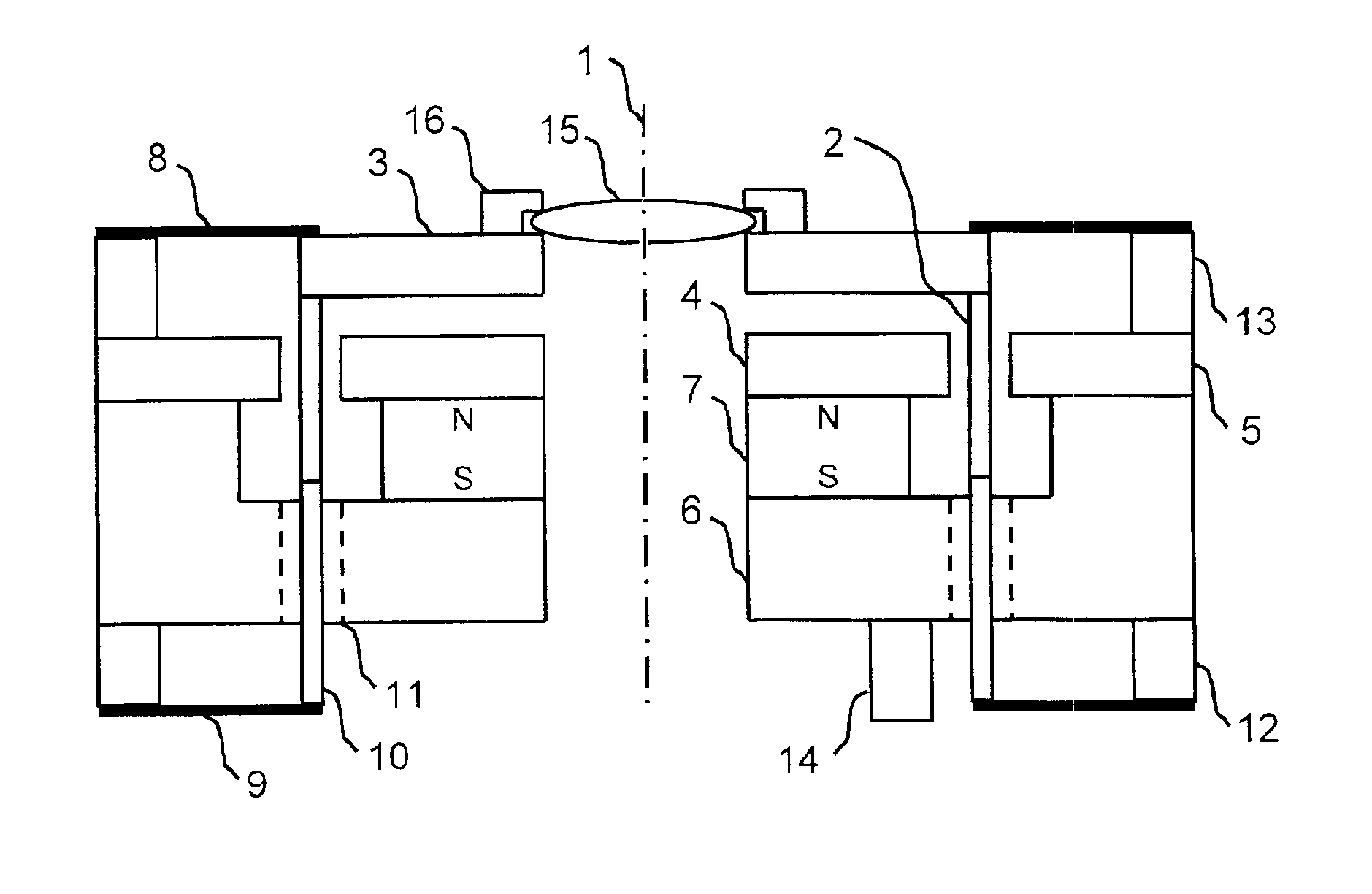
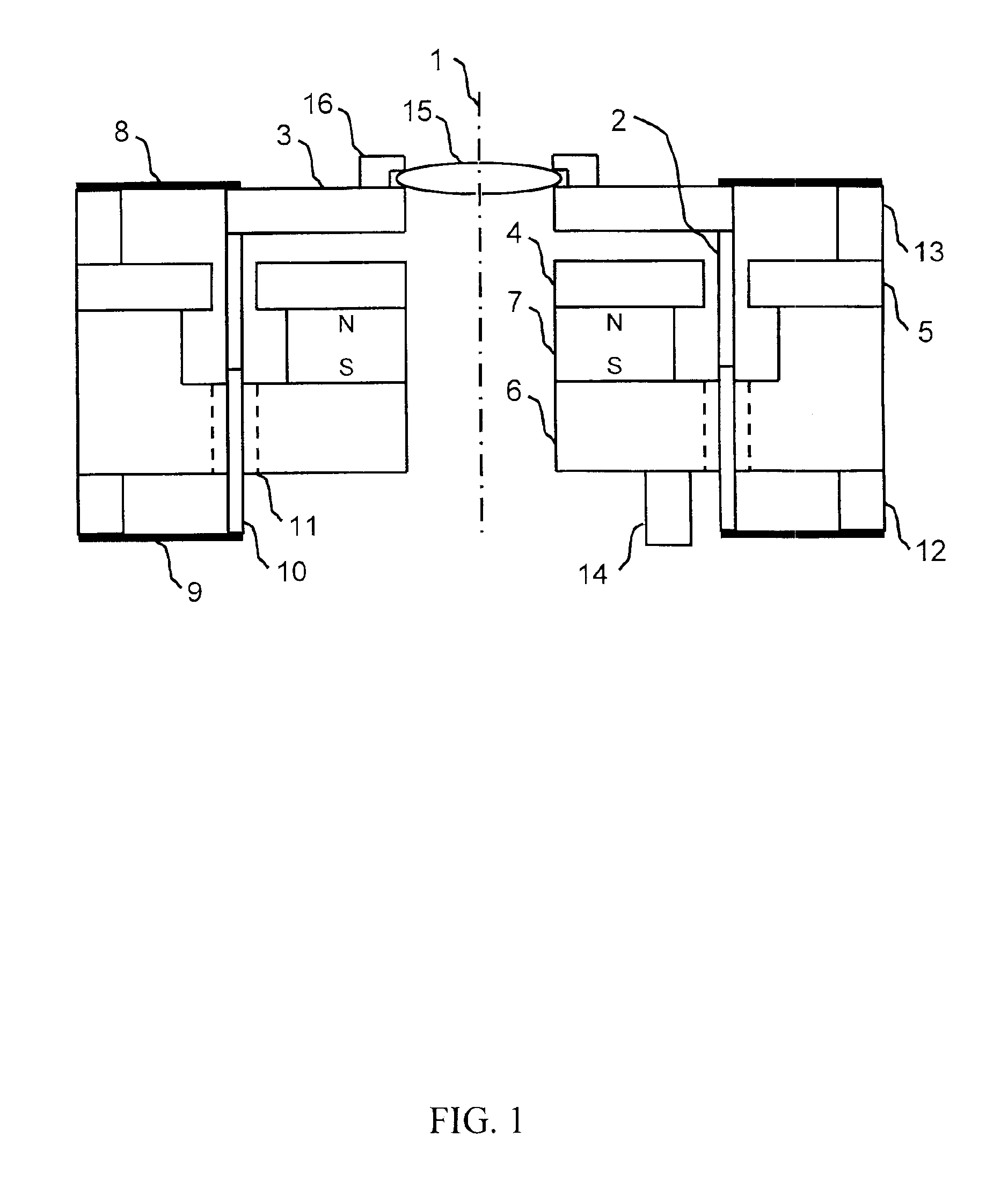
[0019]The present invention provides a means to position an optical element along an optical axis precisely and quickly without lateral or angular perturbations. The present invention is a moving coil linear motor positioning stage with a concentric aperture. The advantages of the present invention are its speed and precision, and the positioning motion has no lateral or angular components.

[0020]The details of the present invention can be implemented in numerous variations of configuration and components. In any case the basic concept is the same. Various types or configurations of flexures or other linear bearings could be used to guide the moving assembly. Various types or configurations of position sensing devices could be used.

[0021]FIG. 1 shows a cross-sectional diagram of the present invention on which and Optical Element 15 is mounted. The present invention is cylindrically symmetric about a Central Axis 1, particularly the moving mass. A useful clear aperture is formed by a ...


PUM


Abstract

A moving coil linear motor positioning stage with a concentric aperture is disclosed. The present invention relates to positioning an element or device such as an optic or lens. The apparatus is ideal for moving an optic coaxial with a light beam. The present invention uses a voice coil motor with a cylindrical moving coil and a cylindrical permanent magnet assembly with a radial gap. The moving coil and magnet assemblies have clear apertures concentric with the apparatus and the axis of motion. A pair of planar flexures guides the moving coil. A position-sensing device is used to sense the position of the moving coil to enable fine position control.

Description

CROSS-REFERENCE TO RELATED APPLICATIONS[0001]Not ApplicableSTATEMENT REGARDING FEDERALLY SPONSORED RESEARCH OR DEVELOPMENT[0002]Not ApplicableBACKGROUND OF THE INVENTION[0003]The present invention relates to moving or positioning an element or device such as an optic or lens.[0004]Stages for positioning optics are common, including stages that move an optic along the optical axis. They are frequently used to move an optical element to affect the focus or collimation of an optical beam in an optical system. Such systems are used for applications ranging from microscopes to systems requiring a focused laser beam for drilling. As the precision, accuracy and speed requirements of such systems increases, the old stage designs become inadequate.[0005]The typical optic positioning stage uses one or more linear bearings mounted parallel to but offset from the optical axis. The optic is driven using a screw, which is also mounted, parallel to but offset from the optical axis. This arrangemen...

Claims


Application Information

Patent Timeline
IPC IPC(8): H02K41/035H04R23/00
CPCH02K41/0356H04R23/008H01L2924/01029H01L2924/014H01L2924/10253H01L2924/00
Inventor KNIRCK, JEFFREY G.SWANSON, PAUL A.
Owner EQUIP DESIGN SERVICES INC
Why Eureka
Try Eureka