Light source

Inactive Publication Date: 2005-04-26
HAMAMATSU PHOTONICS KK
View PDF9 Cites 81 Cited by
  • Summary
  • Abstract
  • Description
  • Claims
  • Application Information

AI Technical Summary

Benefits of technology

[0019]In this light source, the light is outputted through the exit window located at the distal end of the projecting portion extending from the predetermined portion, to the outside, and the peripheral region is cooled by the heat sink in contact with the peripheral region of the predetermined portion or the

Problems solved by technology

The cathode naturally deteriorates after long-term use, but Inventor et al. discovered that

Method used


Image

  • Light source
  • Light source
  • Light source

Examples


Example

(First Embodiment)

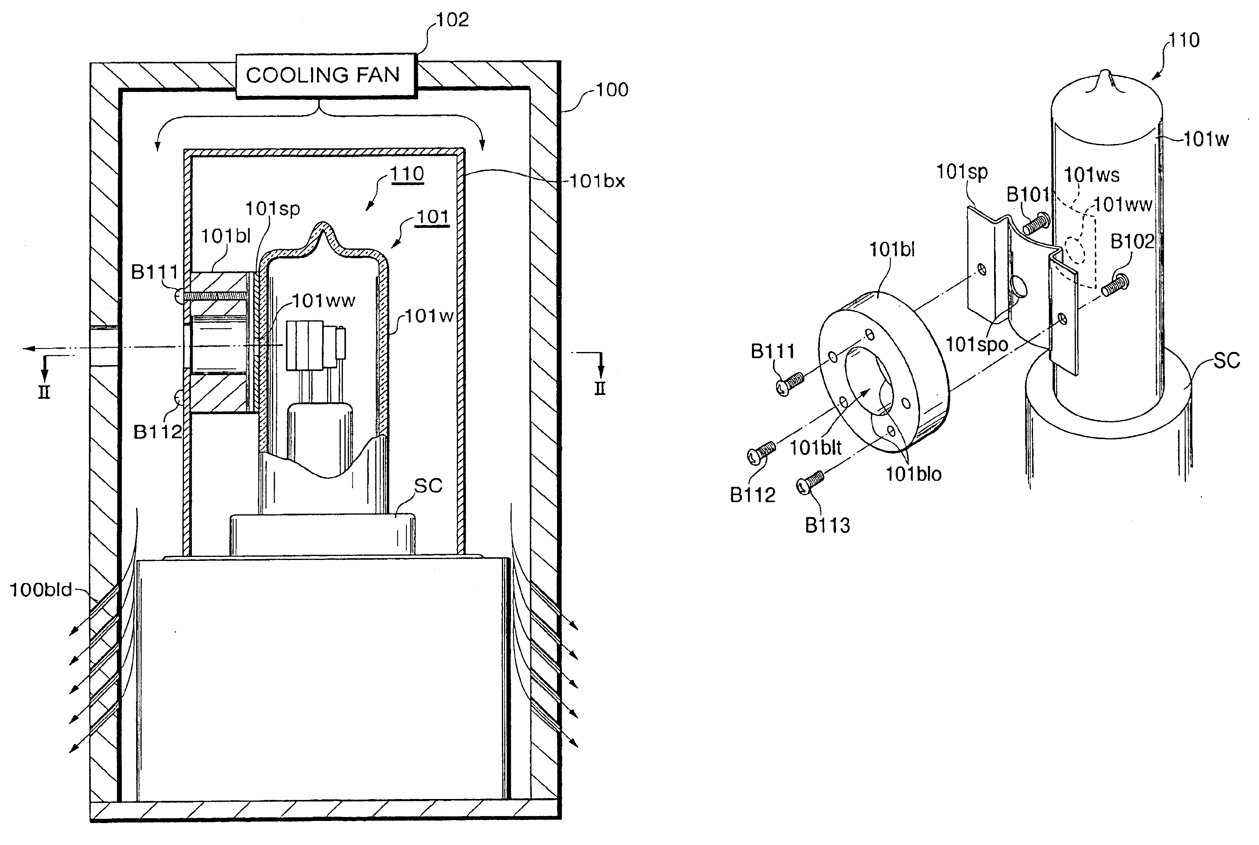
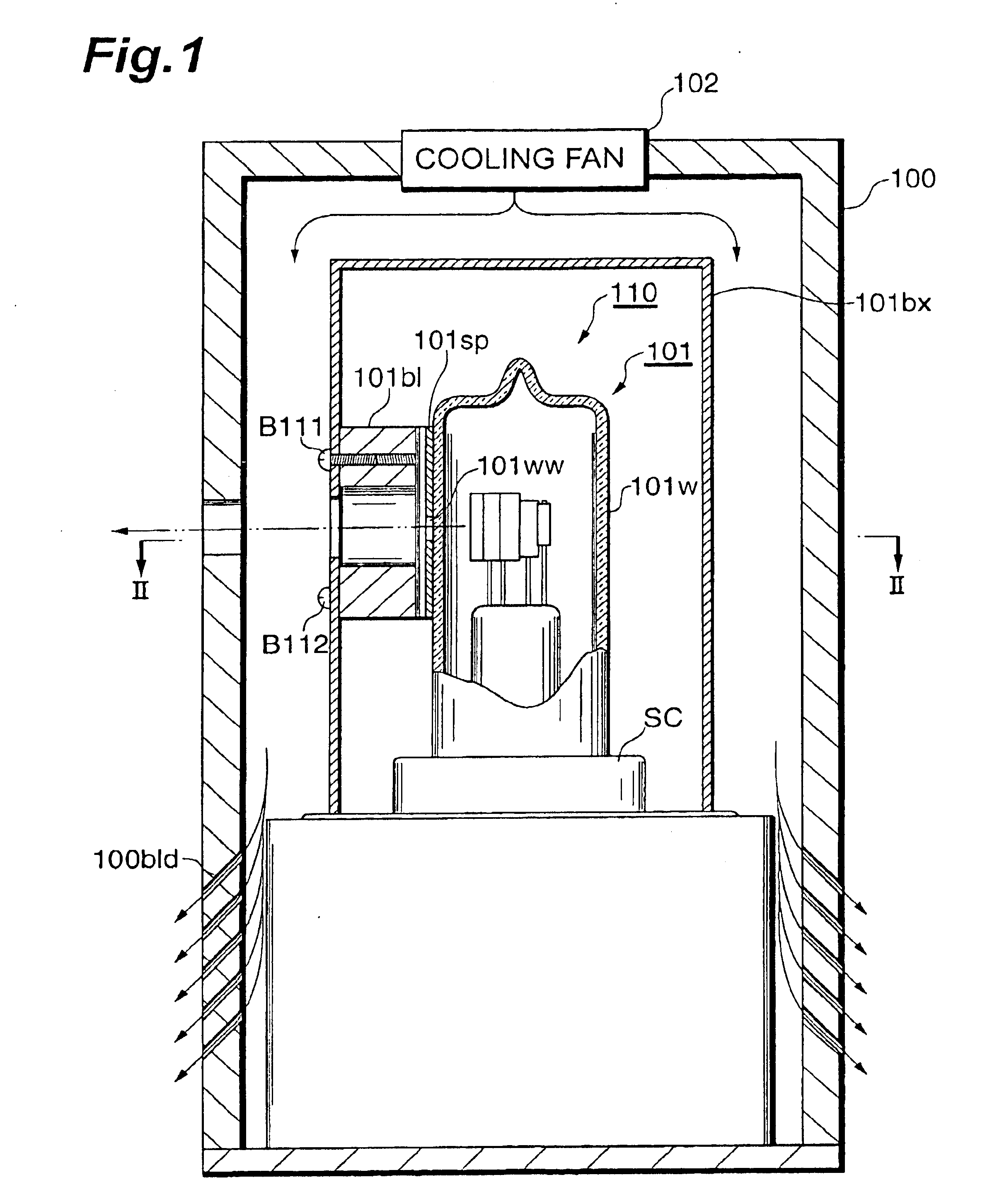
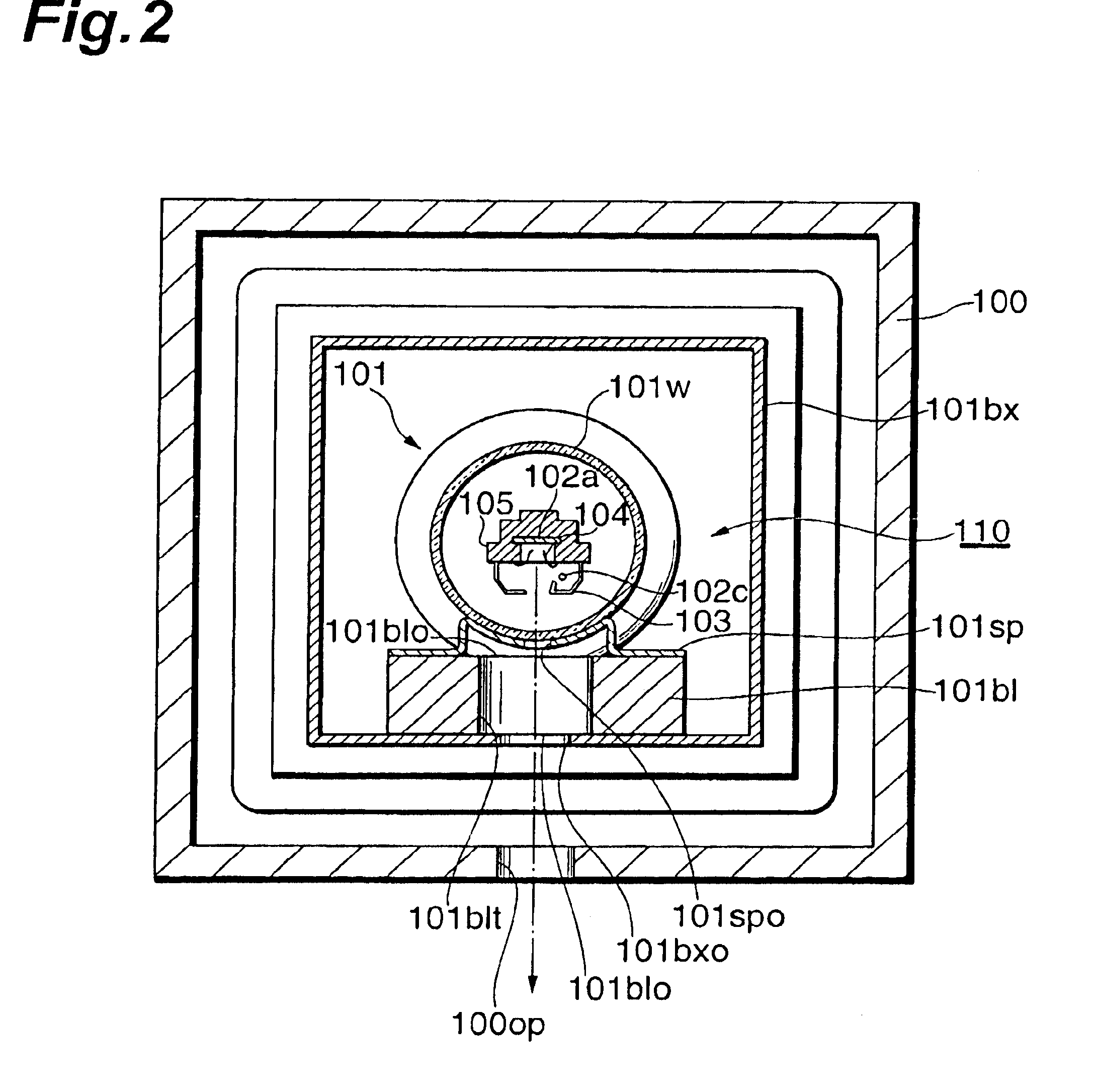
[0047]FIG. 1 is a longitudinal sectional view of the light source as a first embodiment, FIG. 2 a sectional view along a line II—II with arrows of the light source shown in FIG. 1, and FIG. 3 a perspective view of major part of the light source shown in FIG. 1.

[0048]The light source of the present embodiment comprises an outer box 100, an inner box (radiator box) 101bx housed in the outer box 100, and a discharge tube 110 placed in the inner box 101bx. The discharge tube 110 is mounted on a socket SC fixed to a bottom plate of the inner box 101bx, and the exterior surface of the inner box 101bx is cooled by a cooling fan 102 disposed in the top region of the outer box 100. Air taken in from the cooling fan 102 flows through vent holes 100bld formed in the side wall of the outer box 100, to the outside.

[0049]The discharge tube 110 comprises an airtight envelope (glass bulb) 101 having a cylindrical side wall 101w. A gas such as deuterium or the like is sealed in the...

Example

(Second Embodiment)

[0063]FIG. 8 is a longitudinal sectional view of the light source as a second embodiment, FIG. 9 a sectional view along a line II—II with arrows of the light source shown in FIG. 8, and FIG. 10 a perspective view of major part of the light source shown in FIG. 8.

[0064]The light source of the present embodiment comprises an outer box 200, an inner box (radiator box) 201bx housed in the outer box 200, and a discharge tube 210 placed in the inner box 201bx. The discharge tube 210 is mounted on a socket SC fixed to a bottom plate of the inner box 201bx, and the exterior surface of the inner box 201bx is cooled by a cooling fan 202 disposed in the side wall of the outer box 200. Air taken in from the cooling fan 202 flows through vent holes 200bld formed in the side wall of the outer box 200, to the outside.

[0065]The deuterium discharge tubes can suffer degradation of stability of light output because of fluctuation of outside air temperature, whereas the present embod...

Example

(Third Embodiment)

[0082]FIG. 12 is a longitudinal sectional view of the light source as a third embodiment, FIG. 13 a sectional view along a line VI—VI with arrows of the light source shown in FIG. 12, FIG. 14 a sectional view along a line VII—VII with arrows of the light source shown in FIG. 12, and FIG. 15 a perspective view of major part of the light source shown in FIG. 12.

[0083]The light source of the present embodiment is different from the second embodiment in that the spring member 201sp surrounds the side wall of the discharge tube 210 and the block 201bl thermally connected therewith is not mounted on the top region of the radiator box 201bx but mounted on the side wall thereof.

[0084]The spring member 201sp will be described first. The spring member 201sp has an approximately cylindrical interior surface and this interior surface is in contact with the side wall of the cylindrical discharge tube envelope 201. The peripheral ends of the spring member are not connected to ea...


PUM


Abstract

In a light source, a heat sink is in contact with a side-on type discharge tube 110. The heat sink is in contact with a peripheral region 110ws around an exit window 101ww of the discharge tube 110. The heat sink consists of a spring member 101sp kept in direct contact with the peripheral region 101ws, and a radiating block 101bl which connects the spring member 101sp to a radiator box 101bx. Since materials made by sputtering or the like of electrodes in the discharge tube 110 mostly attach to the peripheral region 101ws of side wall 101w, it is feasible to decrease the amount of materials attaching to the exit window 101ww and, in turn, lengthen the lifetime of the discharge tube. Another light source may be constructed in structure in which the heat sink is in contact with a head-on type discharge tube or in structure in which light is outputted from a projecting portion.

Description

TECHNICAL FIELD[0001]The present invention relates to a lamp having a discharge tube such as a deuterium discharge tube, a xenon flash tube, or the like.BACKGROUND ART[0002]A lamp utilizing the microwave is described in Japanese Patent Application Laid-Open No. 07-182910. The lamp described in the Japanese application is configured to seal a gas in an envelope and irradiate the gas with the microwave to excite the gas, thereby inducing emission of light. The gas contains a fluorine base gas, the fluorine base gas etches the internal surface of the silica glass envelope, and Si impurities made by the etching adhere to the internal surface of the envelope. Then, the lamp described in the Japanese application has a cooling pipe penetrating the interior of the envelope and is arranged to attach the impurities made by the etching with the fluorine gas, to the cooling pipe.DISCLOSURE OF THE INVENTION[0003]Meanwhile, there are the conventionally known discharge tubes utilizing arc discharg...

Claims


Application Information

Patent Timeline
IPC IPC(8): H01J61/00H01J61/52H01J61/68H01J61/84H01J61/90H01J61/02
CPCH01J61/523H01J61/90H01J61/68
Inventor KURASHIMA, TATSUOSUYAMA, KEIJIHARADA, NOBUHARUMAKINO, KOUJI
Owner HAMAMATSU PHOTONICS KK
Why Eureka
Try Eureka