Graphical display for aircraft navigation

a technology for aircraft navigation and graphical display, applied in the field of electronic instruments, can solve the problems of not providing sufficient navigation information to the pilot, difficult to add new information in a manner, and cannot replace unrelated essential information

Inactive Publication Date: 2005-04-26
HONEYWELL INT INC
View PDF21 Cites 71 Cited by
  • Summary
  • Abstract
  • Description
  • Claims
  • Application Information

AI Technical Summary

Benefits of technology

[0036]FIG. 13 illustrates the condition where EPU winglet 122 has width 2013 that is smaller than RNP width 206, but because of large CD distance 2313, upper boundary 122U of EPU winglet 122 lies outside upper RNP boundary 260. This is a Potential Hazard condition and appropriate warning should result. FIG. 14 shows the situation where EPU width 2014 has expanded to exceed RNP width 206 (or RNP has shrunk to be less than EPU) and both upper and lower boundaries 122U, 122L of EPU winglet 122 lie outside RNP boundaries 260, 240. This is also a Potential Hazard condition and appropriate warning results.
[0037]As previously discussed, appropriate warnings can be a change in color of the EPU winglet and other symbols, flashing of the EPU winglet and other symbols, an audible alarm or a combination of such. Based on the description herein, persons of skill in the art will conceive of other means of providing warning of the Potential Hazard condition. Those discussed in connection with the lateral CDI 96 also apply to the vertical CDI 100.
[0038]A method is described for indicating when a potentially unsafe aircraft operating condition is existent. The method comprises: determining first and second outer boundaries of the RNP; determining third and fourth opposed outer boundaries of the EPU in a first direction substantially paral

Problems solved by technology

One of the limitations of prior art PFDs is that they do not provide sufficient navigation information to the pilot when the plane is in highly restricted airspace or if they provide such information it is not presented in an easily comprehended way that relates to most pilot's previous experience.
Because of the already crowded and busy nature of the PFD screen, it is difficult to add new information in a manner that can be easily and quickly grasped by the pilot.
However, it cannot replace unrelated essential information.
While this approach provides more information for operation in an RNP region than, say, the display of FIG. 1 it is less than optimal.
Among its limitations are: (i) combining t

Method used


Image

  • Graphical display for aircraft navigation
  • Graphical display for aircraft navigation
  • Graphical display for aircraft navigation

Examples


Embodiment Construction

[0017]The following detailed description of the invention is merely exemplary in nature and is not intended to limit the invention or the application and uses of the invention. Furthermore, there is no intention to be bound by any theory presented in the preceding background of the invention or the following detailed description of the invention.

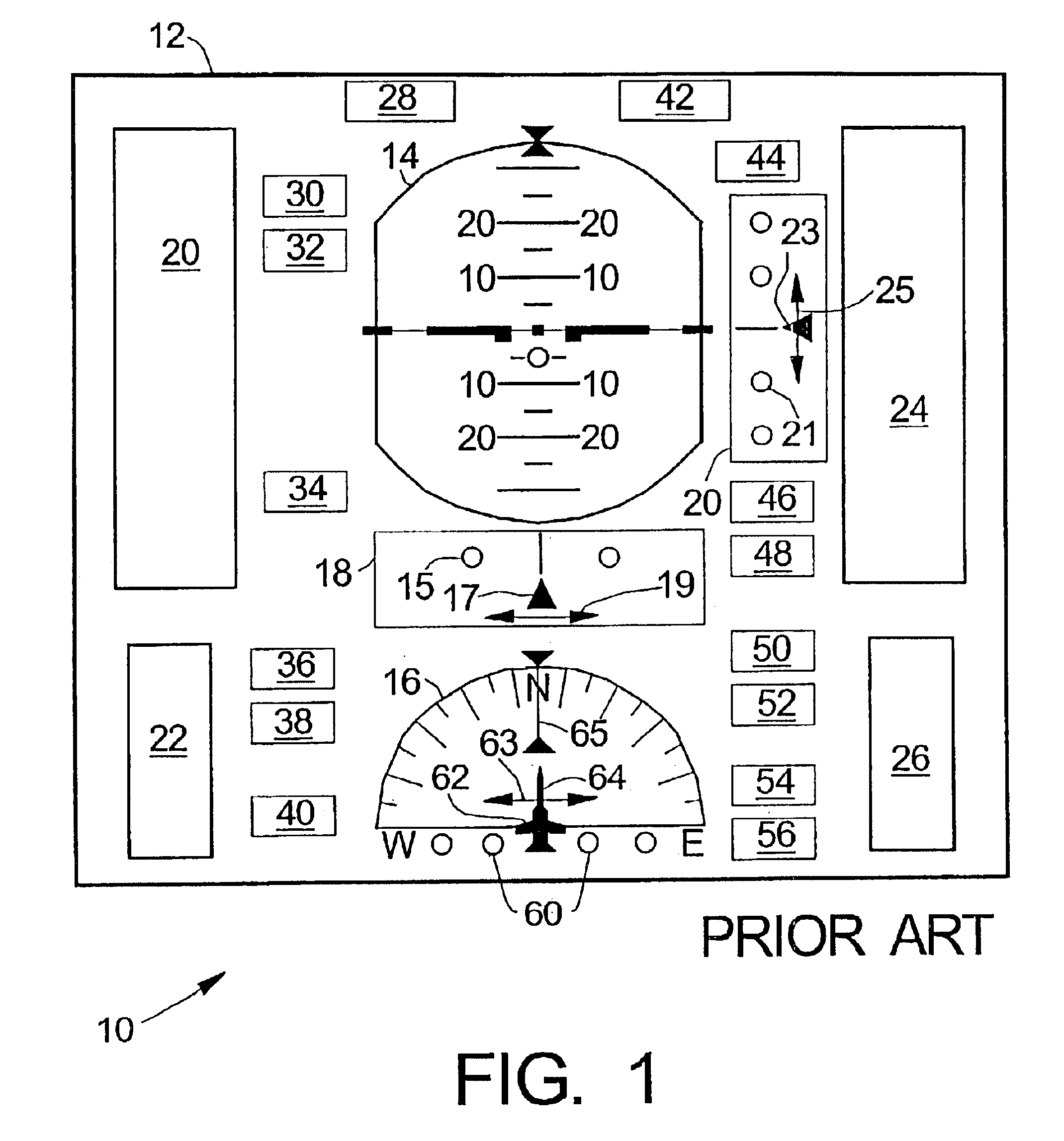
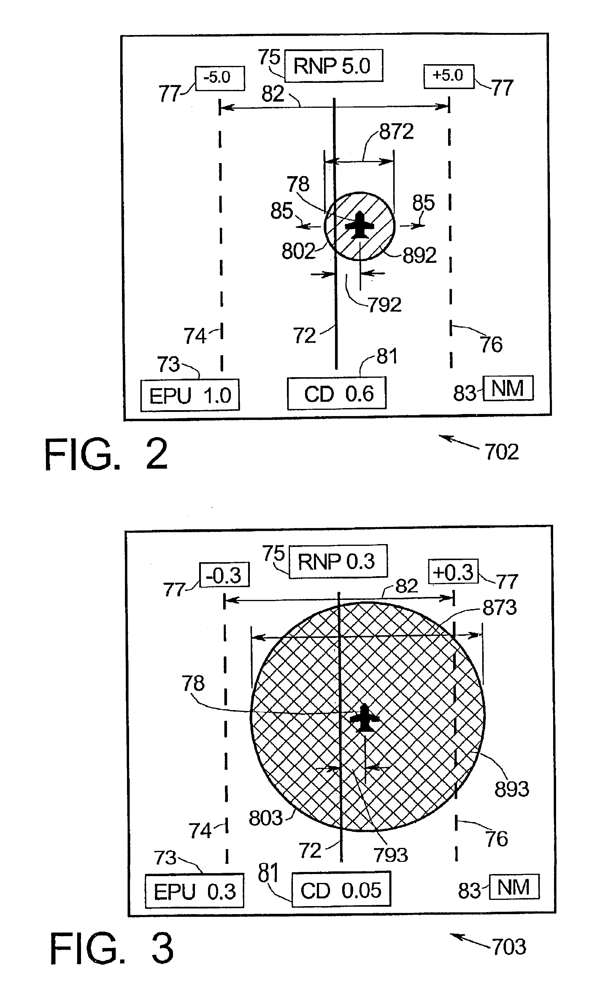
[0018]FIG. 2 is a schematic presentation of display 702 showing RNP, EPU and course deviation (CD) information separately and in a graphical way that intuitively resembles the actual geometry of the flight path situation. Central line 72 represents the planned aircraft course (PAC). Parallel, spaced-apart lines 74, 76 show the RNP boundaries separated by distance 82 corresponding to twice the RNP value. The RNP value is conveniently displayed in boxes 75, 77. In this example RNP is ±5.0 nautical miles (NM). Small aircraft symbol 78 shows the actual aircraft position relative to the RNP boundaries and PAC 72. In this example, aircraft symbol ...


PUM


Abstract

Methods and apparatus are provided for indicating safe or potentially hazardous operating conditions of an aircraft in a required navigational performance (RNP) environment. The apparatus comprises a course deviation display field with first and second markers defining outer boundaries of the RNP width and a central marker indicating the desired course within the RNP width, an aircraft estimated position uncertainty (EPU) marker in the display field whose size corresponds to the EPU relative to the RNP and a current aircraft position marker coupled to the EPU marker and moving therewith as the aircraft position changes with respect to the RNP width. The display desirably changes color and/or flashes to alert a pilot to a potentially hazardous condition when an outer boundary of the EPU marker approaches to within a predetermined guard-band distance of or overlaps either of the first or second markers. An audible warning can be included.

Description

FIELD OF THE INVENTION[0001]The present invention generally relates to electronic instrumentation such as flight control instrumentation, and more particularly to displays providing improved presentation of course deviation, position uncertainty and potential hazard warnings in a required navigation performance (RNP) environment.BACKGROUND OF THE INVENTION[0002]Effective flight management is closely related to providing accurate and timely information to the pilot. This should be done in a manner that succinctly but accurately conveys to the pilot information important to the safe operation of the aircraft. United States Patents or Patent Applications U.S. Pat. Nos. 5,359,890, 5,412,383, 6,118,385, 6,178,379 and U.S.-2003004619 describe various primary avionics systems including flight display systems and related apparatus. A principal flight instrumentation display is the Primary Flight Display (PFD) on which is shown information about course, speed, altitude, rate of climb and oth...

Claims


Application Information

Patent Timeline
IPC IPC(8): G01C23/00
CPCG01C23/00
Inventor SELK, II, LOUIS G.FRAZIER, THOMAS G.
Owner HONEYWELL INT INC
Why Eureka
Try Eureka