Zero clearance receptacle design for single mode optical fiber connectors

a technology of optical fiber connectors and receptacles, applied in the field of optical connectors, can solve the problems of difficult, time-consuming, expensive, etc., and achieve the effect of reducing the number of optical fibers

Inactive Publication Date: 2005-04-26
II VI DELAWARE INC
View PDF4 Cites 13 Cited by
  • Summary
  • Abstract
  • Description
  • Claims
  • Application Information

AI Technical Summary

Benefits of technology

[0011]A zero-clearance optical receptacle according to the principles of the present invention includes an internally fluted V-groove. Such zero-clearance optical receptacles are beneficially dimensioned to receive an optical fiber ferrule on two surfaces that define the V-groove. The V-groove positions the center of the optical fiber ferrule at a defined, rigidly fixed, consistent position, plug-in after plug-in. Beneficially, the zero-clearance optical receptacle further includes a slot that receives ...

Problems solved by technology

Coupling optical elements, such as Vertical Cavity Surface Emitting Lasers (VCSELs), with optical fibers is a relatively difficult, time consuming, and expensive task.
Complicating the problem is that the physical alignment must remain accurate over both time and temperature.
While generally successful, such prior art methods are, as stated, relatively difficult and expensive to implement.
Compounding physical alignment problems is ...

Method used


Image

  • Zero clearance receptacle design for single mode optical fiber connectors
  • Zero clearance receptacle design for single mode optical fiber connectors
  • Zero clearance receptacle design for single mode optical fiber connectors

Examples


Embodiment Construction

[0021]Reference will now be made in detail to various embodiments of the present invention, examples of which are illustrated in the accompanying drawings.

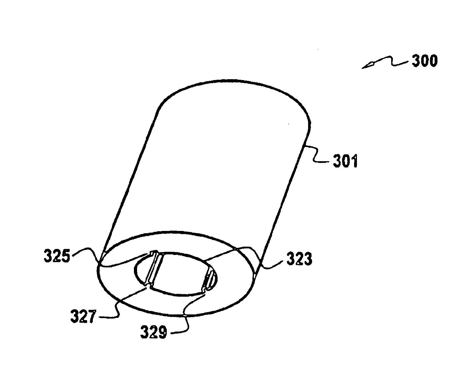
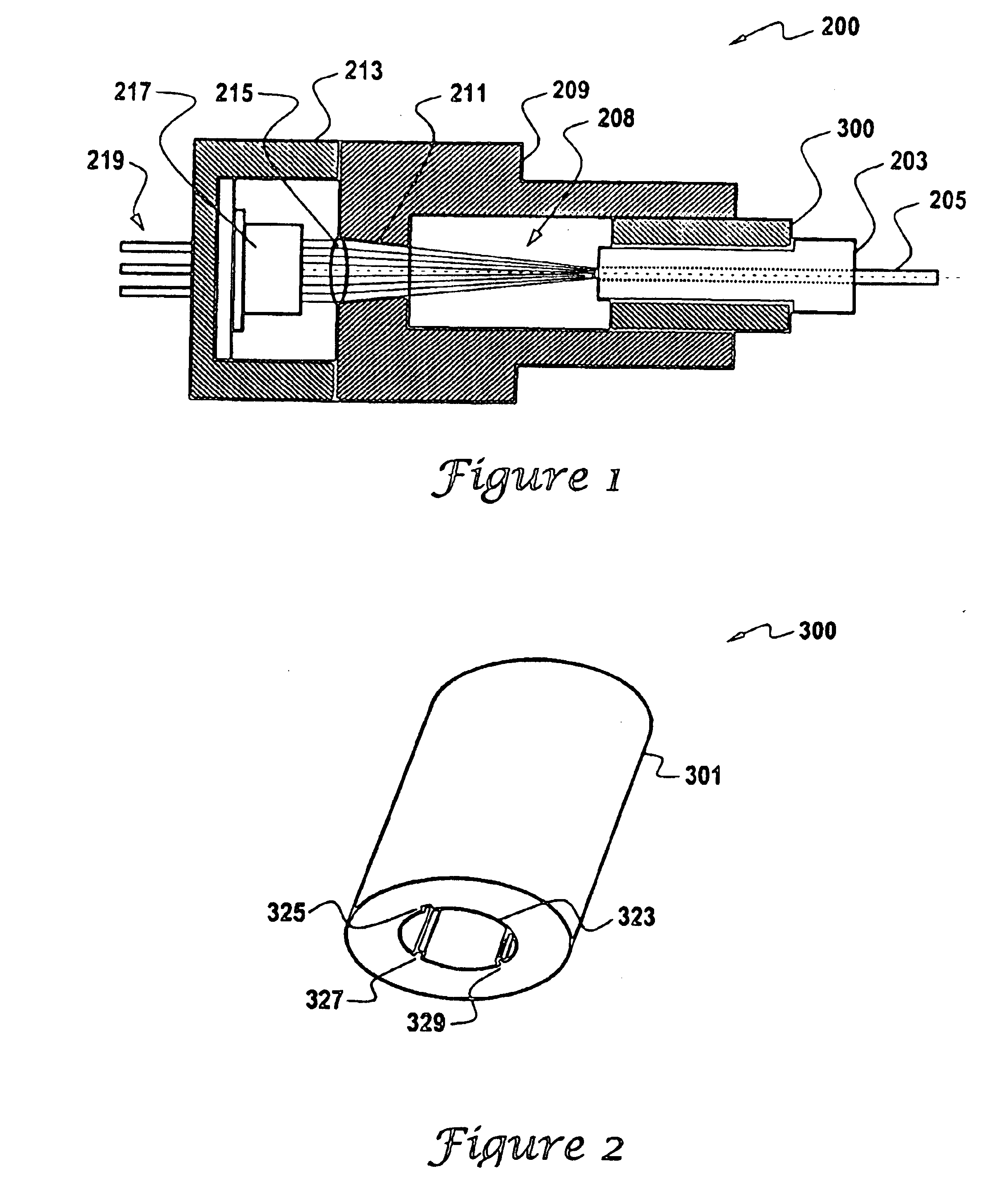
[0022]FIG. 1 illustrates an optical coupler 200 that is in accord with the principles of the present invention. That optical coupler includes a body 209 that has a central channel 208. The central channel 208 is dimensioned to receive a zero-clearance optical receptacle 300, which is described in more detail subsequently. In turn, the zero-clearance optical receptacle 300 receives an optical fiber ferrule 203 that retains an optical fiber 205.

[0023]Still referring to FIG. 1, the optical coupler 200 includes an opening 211 that is axially aligned with the central channel 208. One end of the opening 211 is dimensioned to receive a lens 215. The optical coupler 200 further includes a base 213 that receives an optical element 217 having electrical leads 219. The optical element 217 can be a light emitter, such as a VCSEL, or an optica...


PUM


Abstract

A zero-clearance receptacle for single mode optical fiber couplers. The zero-clearance receptacle includes an internally fluted V-groove formed by internally extending legs. The zero-clearance receptacle uses the fundamental action of the V-groove to accurately locate an optical fiber ferrule inserted into the zero-clearance receptacle in the radial direction. The zero-clearance receptacle further includes a slot that receives a biasing element, such as a spring, that biases the optical ferrule against the V-groove legs. This enables accurate positioning of an optical fiber in the optical ferrule relation to an optical element such as a VCSEL or a photoreceptor. The zero-clearance receptacle beneficially fits into an optical coupler, which may have a lens.

Description

CROSS-REFERENCE TO RELATED APPLICATIONS[0001]Not applicable.BACKGROUND OF THE INVENTION[0002]1. Field of the Invention[0003]The present invention relates to optical connectors.[0004]2. Discussion of the Related Art[0005]Coupling optical elements, such as Vertical Cavity Surface Emitting Lasers (VCSELs), with optical fibers is a relatively difficult, time consuming, and expensive task. One reason for this is that optical coupling requires precise physical alignment between the optical fiber and the optical element. Complicating the problem is that the physical alignment must remain accurate over both time and temperature. For example, when coupling an optical element to a single mode optical fiber a physical alignment that is accurate within a micron or so radially, and between 10 and 15 microns axially, over the full temperature range and over the life of the product can be required.[0006]Optical connectors are used to couple optical fibers to optical elements. A primary task of an ...

Claims


Application Information

Patent Timeline
IPC IPC(8): G02B6/36G02B6/42
CPCG02B6/4292G02B6/3636
Inventor LEE, JAMES C.BLASINGAME, RAYMOND W.CHEN, BO SULI, BERNARD Q.ORENSTEIN, JAMES D.
Owner II VI DELAWARE INC
Why Eureka
Try Eureka