Network for distributing signals to a plurality of user equipment

Inactive Publication Date: 2005-04-26
PRYSMIAN CAVI E SISTEMI ENERGIA
View PDF9 Cites 36 Cited by
  • Summary
  • Abstract
  • Description
  • Claims
  • Application Information

AI Technical Summary

Benefits of technology

[0046]Moreover, since the optical fibres of the invention have a simple refractive index profile, they are highly compatible with single-mode optical fibres according to the ITU-T G 652 standard, also havin

Problems solved by technology

Nevertheless the latter, when present, is strongly disadvantaged by the

Method used


Image

  • Network for distributing signals to a plurality of user equipment
  • Network for distributing signals to a plurality of user equipment
  • Network for distributing signals to a plurality of user equipment

Examples


Embodiment Construction

[0117]FIG. 9 shows an embodiment of an optical fibre 10 according to the invention, comprising an internal region 14, called core, into which an optical signal is transmitted, and an external annular region 12, called cladding. Cladding 12 has a lower refractive index with respect to that of core 14 so as to confine the transmitted signal into the latter.

[0118]Typically, both core 14 and cladding 12 are made of a silica-based glass material, and the refractive index difference between core 14 and cladding 12 is obtained by incorporating suitable additives (dopants) into the glass matrix of core 14 and / or of cladding 12.

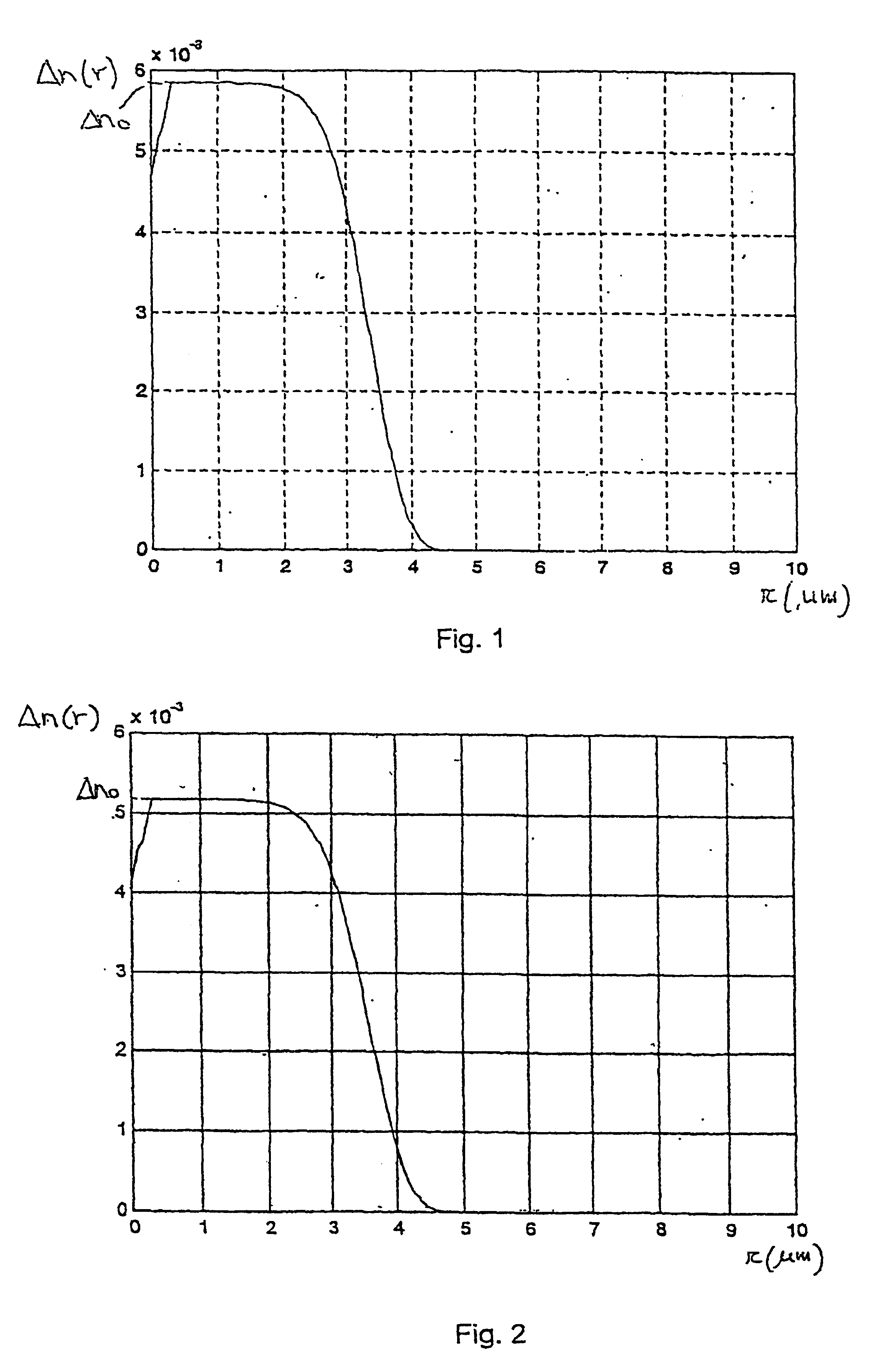
[0119]Based on the radial distribution of the dopants into core 14 and cladding 12 of the optical fibre 10, a certain refractive index profile Δn(r), is obtained, where Δn(r) refers to the refractive index difference between core 14 and cladding 12 as a function of the radial distance r from the longitudinal axis xx of the optical fibre 10.

[0120]Typically, as shown in...


PUM


Abstract

A network for distributing signals to a plurality of user having a distribution unit and a plurality of optical cables adapted to make the distribution unit communicate with the plurality of user equipment. In turn, each optical cable has an optical fibre having a core, a cladding and a predetermined simple refractive index profile Δn(r). Each optical fibre is adapted to guarantee a single-mode propagation at higher wavelengths than about 1260 nm and a few-mode propagation at about 850 nm, and each optical fibre has such refractive index profile Δn(r) as to guarantee macro-bending losses at 1550 nm that are less than about 0.5 dB and an intermodal delay Δτ at 850 nm that is less than or equal to, about 1 ns/Km.

Description

CROSS REFERENCE TO RELATED APPLICATIONS[0001]This application is a national phase application based on PCT / IT01 / 00466, filed Sep. 7, 2001, the content of which is incorporated herein by reference, and claims the priority of Italian Patent Application No. MI2000A001983, filed Sep. 11, 2000, the content of which is incorporated herein by reference, and claims the benefit of U.S. Provisional Application No. 60 / 242,715, filed Oct. 25, 2000, the content of which is incorporated herein by reference.BACKGROUND OF THE INVENTION[0002]1. Field of the Invention[0003]The present invention relates to a signal distribution network from a common branch point to a plurality of user equipment, comprising a distribution unit and a plurality of optical-fibre cables.[0004]The present invention also relates to an optical-fibre cable and to an optical fibre adapted to be used in a signal distribution network.[0005]2. Description of the Related Art[0006]Currently, in the telecommunication field optical te...

Claims


Application Information

Patent Timeline
IPC IPC(8): G02B6/02G02B6/255H04B10/207G02B6/34G02B6/028G02BH04B10/25H04B10/27H04B10/272H04B10/278H04B10/524H04B10/54H04B10/572H04J14/00H04J14/02
CPCG02B6/02266G02B6/02276G02B6/0281G02B6/29377G02B6/2552G02B6/0288G02B6/03611
Inventor OLIVETI, GUIDOPOMARICO, FRANCESCO IVANROBA, GIACOMOSARCHI, DAVIDESARTORI, FRANCESCO
Owner PRYSMIAN CAVI E SISTEMI ENERGIA
Why Eureka
Try Eureka