Optical fiber and optical transmission system

a transmission system and optical fiber technology, applied in the field of optical fiber and optical transmission system, can solve the problems of difficult to significantly reduce nsub>2 /sub>in a quartz-derived optical fiber, complicated refractive index profile development, and high cost, so as to reduce nonlinearity, reduce bending loss, and avoid transmission loss

Inactive Publication Date: 2006-07-11
THE FUJIKURA CABLE WORKS LTD
View PDF12 Cites 49 Cited by
  • Summary
  • Abstract
  • Description
  • Claims
  • Application Information

AI Technical Summary

Benefits of technology

[0015]It is also the objective of the present invention to provide an optical fiber having a relatively simple refractive index profile that can be fabricated at low cost.
[0017]In the present invention, by adjusting the structural parameters of an optical fiber having a refractive index profile of a relating simple structure, it is possible to provide at low cost an optical fiber which has an increased Aeff and a cut-off wavelength that enables single mode propagation in an employed wavelength band selected in the range of 1.53˜1.63 μm. Moreover, bending loss can be reduced to a value that is acceptable to the application.
[0018]As a result, the present invention enables the provision of an optical fiber in which a transmission loss is avoided by reducing nonlinearity in an employed wavelength band selected from the range of 1.53˜1.63 μm. At the same time, a worsening of transmission loss due to the microbending that occur during installation does not readily occur in the present invention's optical fiber, and single mode propagation is assured.
[0019]Further, by combining the present invention's optical fiber with a dispersion compensating optical fiber, it is possible to reduce the degradation of optical signal that is caused by nonlinearity and dispersion characteristics, and to construct an optical transmission system that has excellent transmission characteristics.

Problems solved by technology

Because n2 is a constant value for the material, it is very difficult to significantly decrease n2 in a quartz-derived optical fiber.
A number of designs having complicated refractive index profiles have been developed, however, all of these are quite expensive.
However, when the employed wavelength band is set in the 1.53˜1.63 μm range in the case of a 1.3 μm single mode optical fiber, then bending loss (macrobending loss) increases and there is a worsening of the transmission loss that arises due to the slight bending that occurs during laying of the optical fiber.
However, since this cut-off shift optical fiber is not intended to control nonlinearity, it does not have an Aeff that is large enough for this purpose.

Method used


Image

  • Optical fiber and optical transmission system
  • Optical fiber and optical transmission system
  • Optical fiber and optical transmission system

Examples


embodiment

[0102]Embodiments of the present invention will now be explained in detail.

example 1

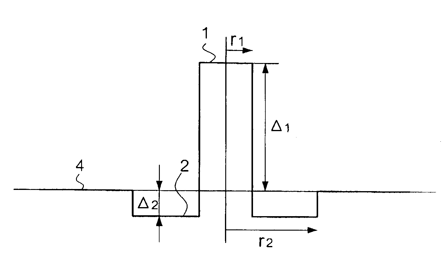
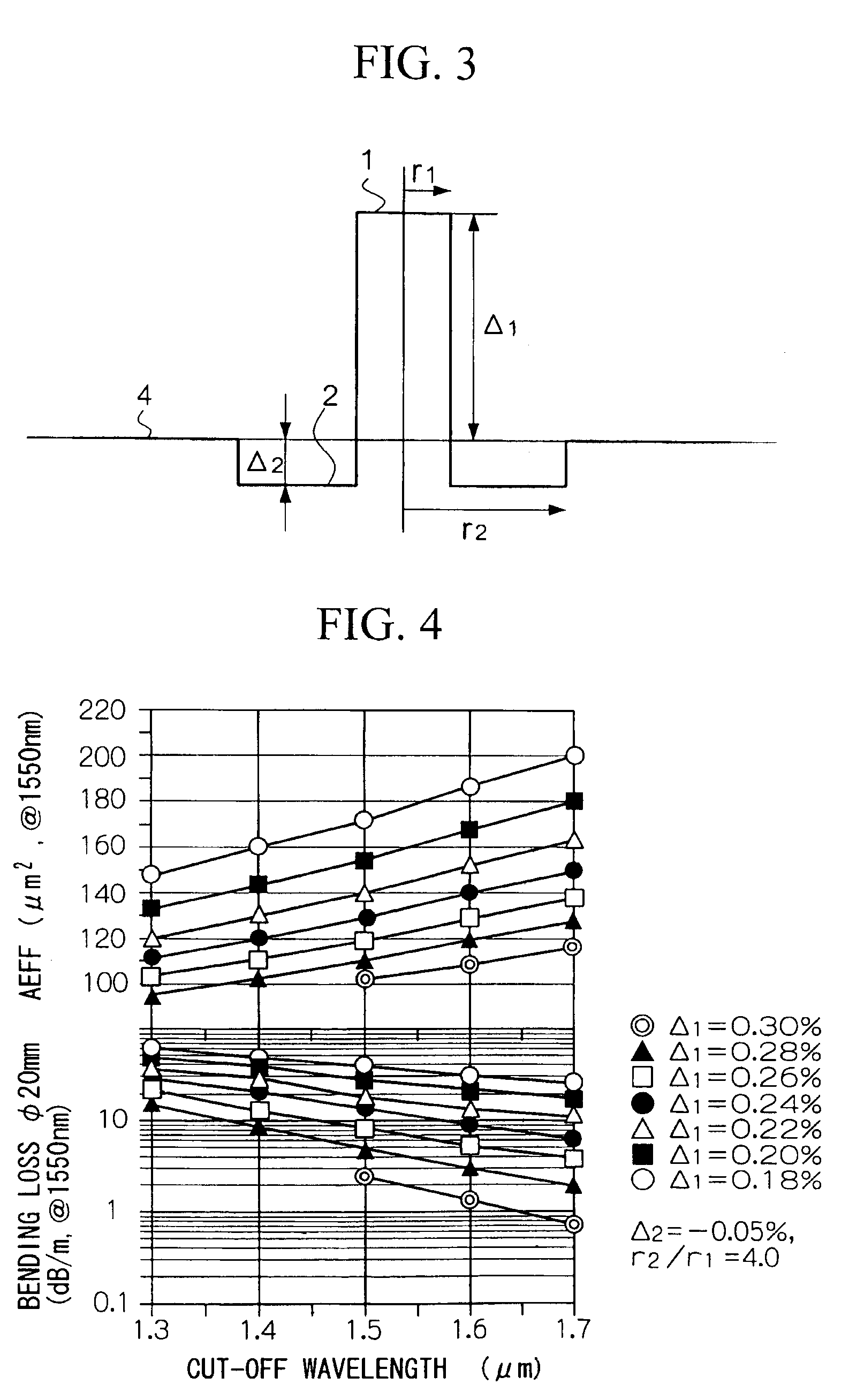
[0103]An optical fiber having the refractive index profile shown in FIG. 3 was fabricated using the VAD method. The central core was comprised of germanium-doped quartz glass, the middle part was comprised of fluorine-doped quartz glass, and the cladding was comprised of pure quartz glass.

[0104]The Δ1 and Δ2 in this optical fiber were 0.24% and −0.05%, respectively. r1 and r2 were 6.6 μm and 26.5 μm, respectively. The outer diameter of the cladding was 125 μm. The characteristics of this optical fiber are shown in Table 1. Each of the characteristic values were measured at 1.55 μm. The cut-off wavelength was measured using the 2 m method.

[0105]

TABLE 1Cut-offWavelengthwavelengthAeffMFDΔ1Δ2r1:r2(μm)(μm)(μm2)(μm)0.24−0.051:4.01.5501.5513212.7bendingincrease inouterlossTrans-sandpaperdiameter(dB / m)missionWavelengthDispersiontensionof2R =lossdispersionslopewinding losscoating20 mm(dB / km)(ps / nm / km)(ps / nm2 / km)(dB / km)(μm)10.20.188+20.7+0.0620.15400

example 2

[0106]An optical fiber was prepared in the same manner as in Example 1, with the exception that the central core was comprised of pure quartz glass and the cladding was comprised of fluorine-doped quartz glass.

[0107]The optical characteristics of this optical fiber were the same as those shown in Table 1 for the optical fiber in Example 1, with exception that the transmission loss was 0.178 dB / km, 0.01 dB / km less than the optical fiber in Example 1.


PUM


Abstract

An optical fiber is fabricated with a refractive index profile having a central core; a middle part provided around the outer periphery of the central core and having a lower refractive index than that of the central core; and a cladding provided around the periphery of the middle part and having a higher refractive index than the middle part and a lower refractive index than the central core. This optical fiber has an effective core area of 120 μm2 or more in an employed wavelength band selected from the range of 1.53˜1.63 μm, and has a cut-off wavelength that is capable of substantially single mode propagation in the aforementioned employed wavelength band. As a result, it is possible to construct an optical transmission system having excellent transmission characteristics in which nonlinearity is decreased.

Description

BACKGROUND OF THE INVENTION[0001]1. Field of the Invention[0002]The present invention relates to an optical fiber and to an optical transmission system employing this optical fiber. More specifically, the present invention relates to an optical fiber having a relatively simple structure, that has an increased effective core area and can reduce nonlinearity in an employed wavelength band selected from the range of 1.53˜1.63 μm, and to an optical transmission system employing this optical fiber.[0003]This application is based on patent applications filed in Japan (Japanese Patent Application No. Hei 11-228904 and No. 2000-12259), the contents of which are incorporated herein by reference.[0004]2. Background Art[0005]As erbium-doped optical fiber amplifiers have entered practical use, systems such as very-long-distance non-repeating relays for wavelengths of 1.53˜1.63 μm have become commercially available. Further, the development of WDM (wavelength division multiplex) transmission has...

Claims


Application Information

Patent Timeline
Patent Type & Authority Patents(United States)
IPC IPC(8): G02B6/02G02B6/036G02B6/34
CPCG02B6/02019G02B6/02266H04B10/2525G02B6/03644G02B6/29377G02B6/29394G02B6/03627G02B6/02238G02B6/02261
Inventor AIKAWA, KAZUHIKOSUZUKI, TAKASHIWADA, AKIRAYAMAUCHI, RYOZOSUZUKI, TAKAAKIMATSUO, SHOICHIROSAITOU, MANABU
Owner THE FUJIKURA CABLE WORKS LTD
Why Eureka
Try Eureka