
System and method for measuring system parameters and process variables using multiple sensors which are isolated by an intrinsically safe barrier

a technology of process variables and sensors, applied in the direction of process and machine control, instruments, and conversion of sensor output using wave/particle radiation, etc., can solve problems such as explosion and dangerous atmospher

Inactive Publication Date: 2005-04-26
SMAR RES CORP
View PDF7 Cites 52 Cited by
  • Summary
  • Abstract
  • Description
  • Claims
  • Application Information

AI Technical Summary

Benefits of technology

[0014]In an exemplary embodiment of the present invention, the system also includes a control interface powered by a further power source. The control interface is configured to receive data representative of the parameter from the control logic arrangement. The control interface may transmit commands to the sensor via the control logic arrangement and / or via the intrinsically safe barrier. Commands can also be forwarded to the sensor via the intrinsically safe barrier.
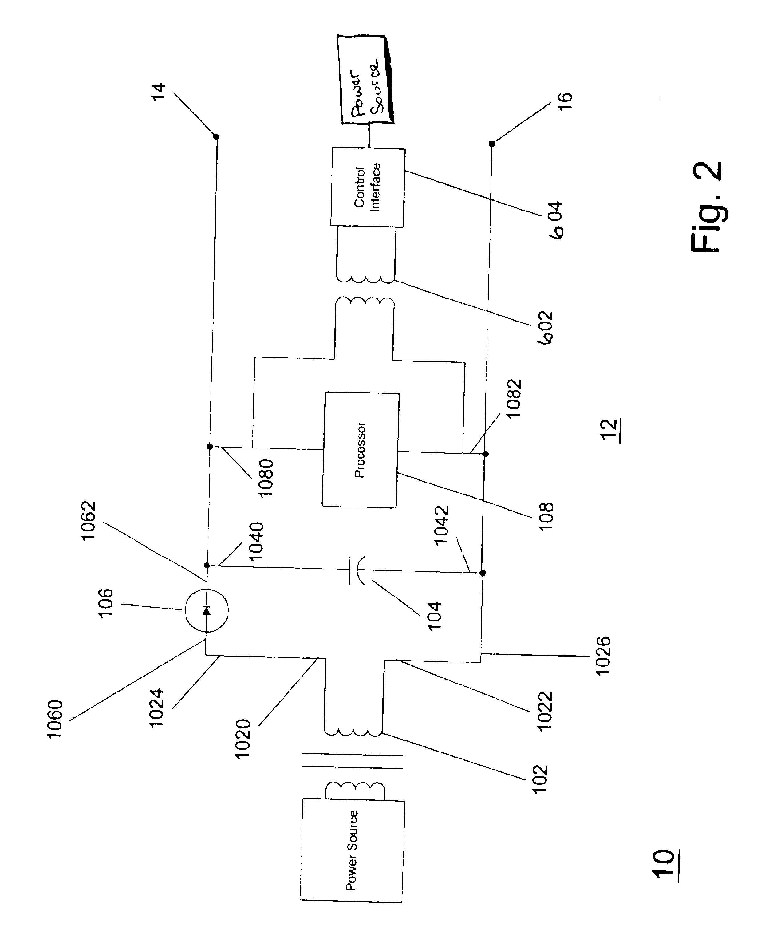
[0015]In another exemplary embodiment of the present invention, the control interface is powered by a further power source. The control interface is configured to receive data representing the parameter from the control logic arrangement, and to transmit commands directly to the sensor. The control logic arrangement can include a transformer having a positive terminal and a negative terminal, a capacitor having a first terminal and a second terminal, and a diode having a cathode and an anode. The anode is electrically connected to the positive terminal of the transformer and the first terminal of the capacitor. The logic arrangement also includes a processor electrically connected to the cathode of the diode, and electrically connected to negative terminal of the transformer and the second terminal of the capacitor. The control logic arrangement can also include a further transformer having a first terminal, a second terminal, a third terminal, and a fourth terminal. Such further transformer can be electrically connected to the processor, and to the processor.
[0016]In yet another exemplary embodiment of the present invention, the logic arrangement can also include a control interface electrically connected to the further transformer. The control interface may be configured to receive data representing the parameter from the control logic arrangement, and to the sensor via the control logic arrangement. The data may representing the process parameter received by the control logic arrangement from the sensor is digital data. In addition, such data can be transmitted using a communications protocol (e.g., a Fieldbus protocol).
[0017]In still another exemplary embodiment of the present invention, the intrinsically safe barrier electrically isolates the sensor from the control logic arrangement. Also, the intrinsically safe barrier can limit the voltage differential over the sensor to a particular limit (e.g., approximately 18 V). In addition, the intrinsically safe barrier limits the amount of current provided to the sensor to a particular current amount (e.g., approximately 120 mA).
[0018]According to a further embodiment of the present invention, the intrinsically safe barrier may include a fuse, a zener diode having a cathode and an anode, and a resistor having a first terminal and a second terminal. The first terminal of the resistor is electrically connected to the cathode of the zener diode and the fuse. The system can include an enclosure, such that the control logic arrangement and the intrinsically safe barrier are located within the enclosure. Also, the control logic arrangement, the intrinsically safe barrier and the sensor may be galvanically isolated from external components.
[0019]In a still further exemplary embodiment of the present invention, the intrinsically safe barrier can be adapted to be operatively connected to a second sensor,. The second sensor is powered by the power source, and configured to transmit data representing a further parameter via the intrinsically safe barrier to the control logic arrangement. The data representative of the second parameter received by the control logic arrangement from the second sensor is digital data which can be transmitted using a communications protocol (e.g., a Fieldbus protocol).

Problems solved by technology

In industrial processes where flammable or explosive materials are handled any leak or spill can cause an explosive and dangerous atmosphere.
This energy-limiting interface and placement thereof restricts the electrical energy in the hazardous-area circuits so that potential electrical sparks or hot spots are too limited and weak to cause any ignition.
In particular, the intrinsically safe barrier limits the power that can be introduced into the hazardous location to energy levels which are safe for the material being handled (or the process being performed) in such area.

Method used


Image

  • System and method for measuring system parameters and process variables using multiple sensors which are isolated by an intrinsically safe barrier
  • System and method for measuring system parameters and process variables using multiple sensors which are isolated by an intrinsically safe barrier
  • System and method for measuring system parameters and process variables using multiple sensors which are isolated by an intrinsically safe barrier

Examples


Embodiment Construction

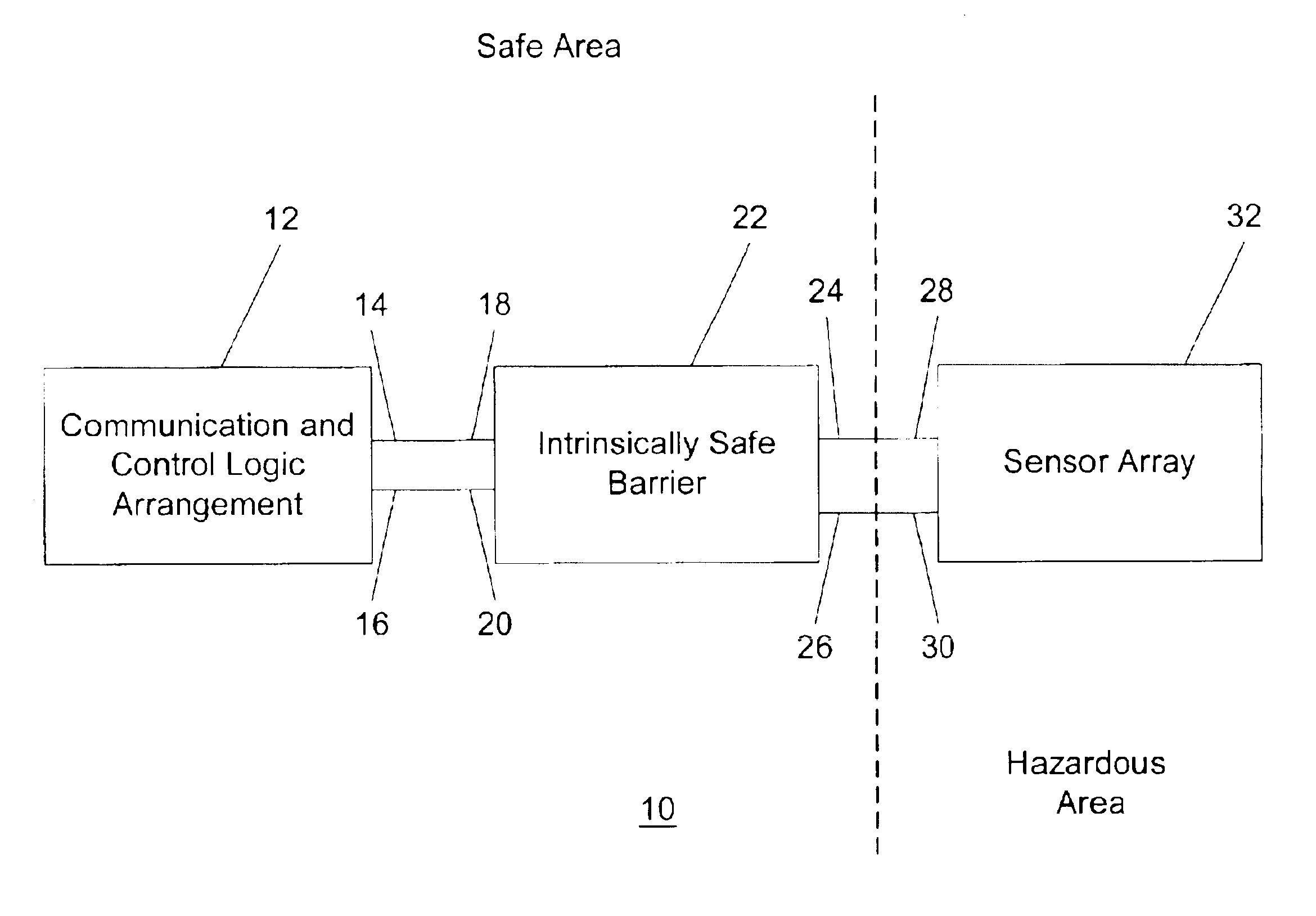
[0028]FIG. 1 illustrates a block diagram of a first exemplary embodiment of a measuring system 10 for sensing various process parameters and variables according to the present invention. The measuring system 10 utilizes a communication and control logic arrangement 12, an intrinsically safe barrier 22 and a sensor array 32 to measure various process parameters. The communication and control logic arrangement 12 preferably provides power for the entire measuring system 10, issues commands to the sensor array 32, and receives information regarding various process parameters and variables from the sensor array 32. The communication and control logic arrangement 12 also includes a first terminal 14 and a second terminal 16 which are connected to a first terminal 18 and a second terminal 20, respectively, of the intrinsically safe barrier 22. The intrinsically safe barrier 22 electrically isolates and protects a particular area (e.g., a protected area) in which no electric sparks are des...


PUM


Abstract

A system for measuring at least one parameter is provided. The system includes a control logic arrangement powered by a power source, and an intrinsically safe barrier operatively connected to the control logic arrangement, and also powered by the same power source. The intrinsically safe barrier is adapted to be operatively connected to at least one sensor which is also powered by the same power source. The sensor is configured to communicate data representing a parameter to the control logic arrangement via the intrinsically safe barrier. In one embodiment, the control logic arrangement, the intrinsically safe barrier and the sensor are galvonically isolated from external components and / or provided in one enclosure.

Description

FIELD OF THE INVENTION[0001]The present invention relates generally to systems and methods for measuring parameters and process variables within a manufacturing environment and more particularly relates a system and method to measuring parameters and process variables within a hazardous environment in which intrinsically safe barriers are utilized.BACKGROUND OF THE INVENTION[0002]In industrial processes where flammable or explosive materials are handled any leak or spill can cause an explosive and dangerous atmosphere. These conditions occur in many industrial environments, most typically in those involving petroleum and other chemicals, process gassers, metal and carbon dust, alcohol, grain, starch, flour, and fibers. To protect both personnel and plant, precautions should be taken within these hazardous areas. In the past, pneumatic controls have been used in these environments to avoid the risk of an electrical spark. Currently, while pneumatic equipment is still utilized, new te...

Claims


Application Information

Patent Timeline
Patent Type & Authority Patents(United States)
IPC IPC(8): G06F19/00H02H3/20H04B3/00G01DG01D3/08G01D5/48
CPCG01D21/00G01D3/08
Inventor SELLI, BASILIO
Owner SMAR RES CORP
Learn More