
Strip casting apparatus

a casting apparatus and strip technology, applied in the direction of moulding machines, vehicle cleaning,foundry moulding apparatus, etc., can solve the problems of contamination and damage to the casting roll surface, and achieve the effect of more effective cleaning

Inactive Publication Date: 2005-05-03
NUCOR CORP
View PDF5 Cites 24 Cited by
  • Summary
  • Abstract
  • Description
  • Claims
  • Application Information

AI Technical Summary

Benefits of technology

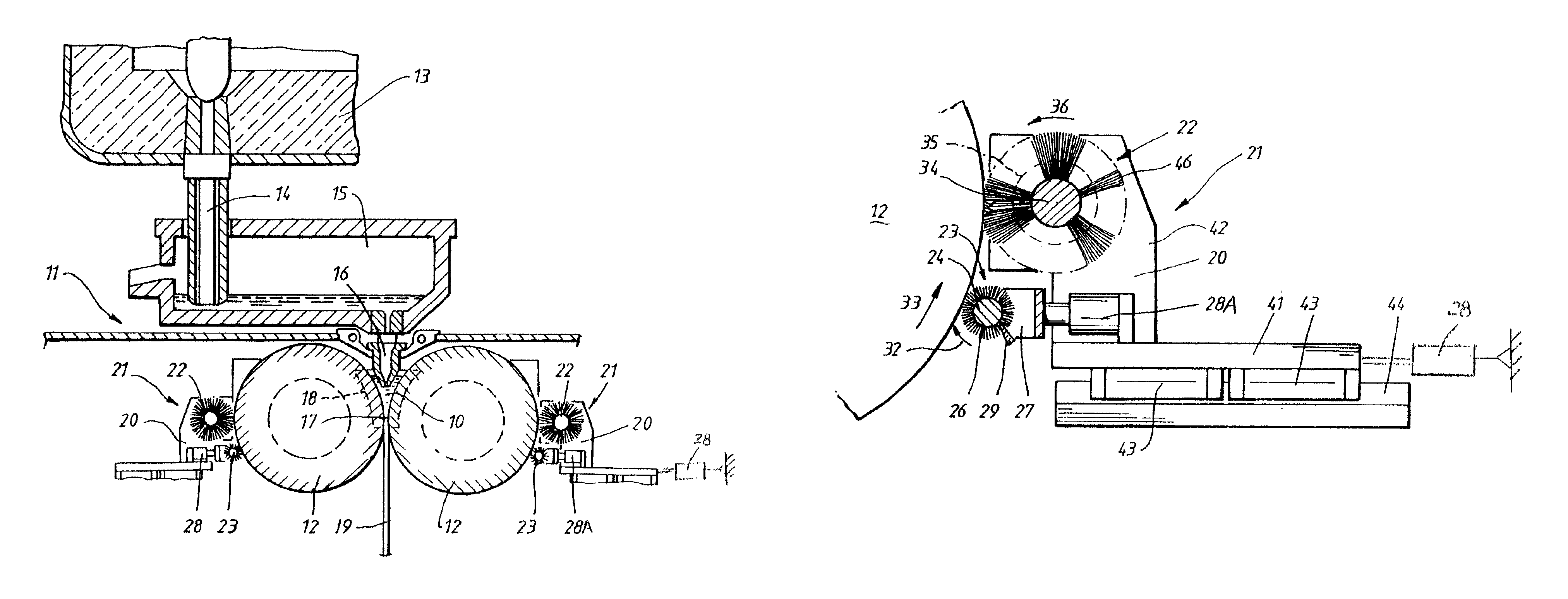
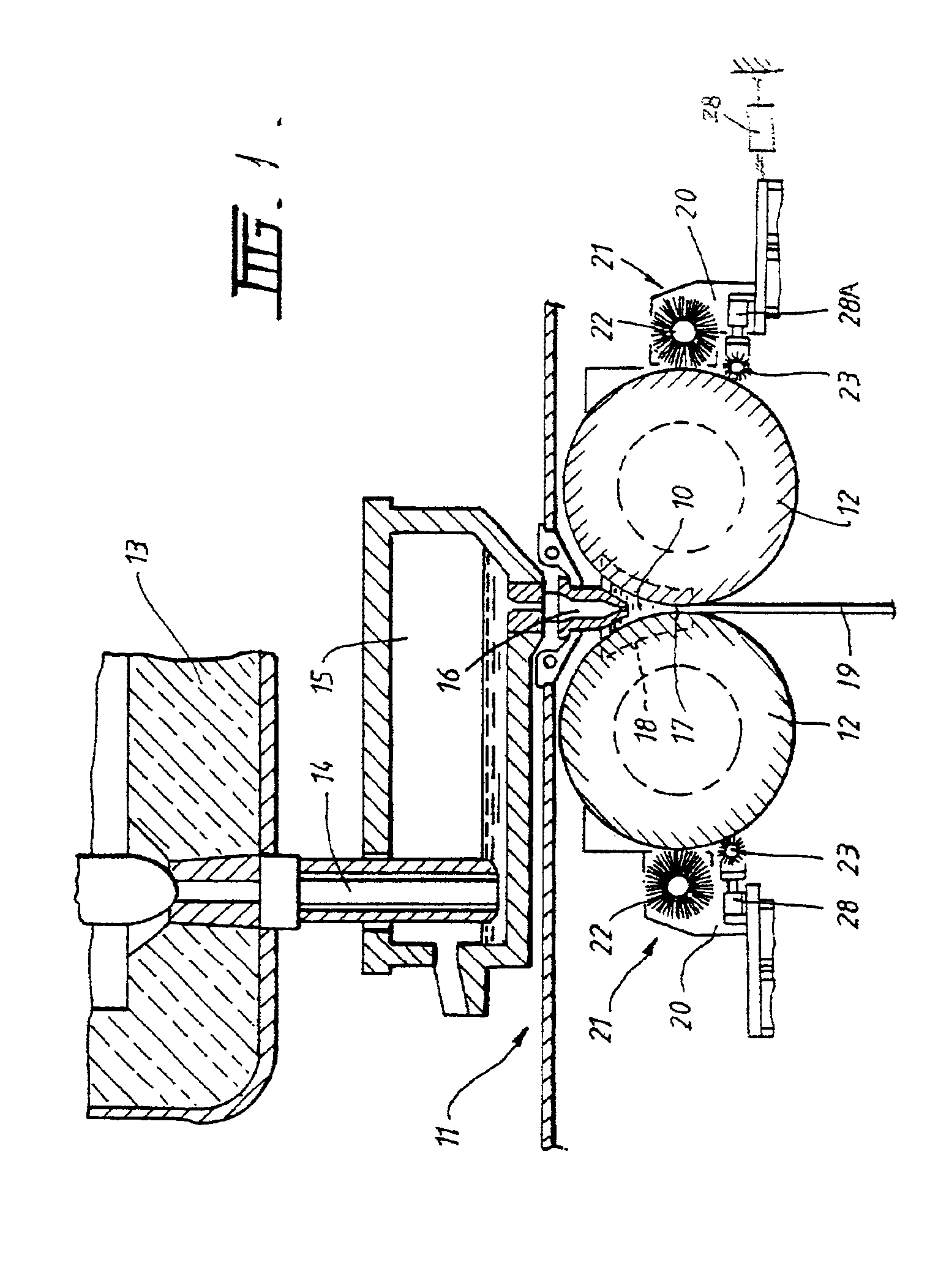
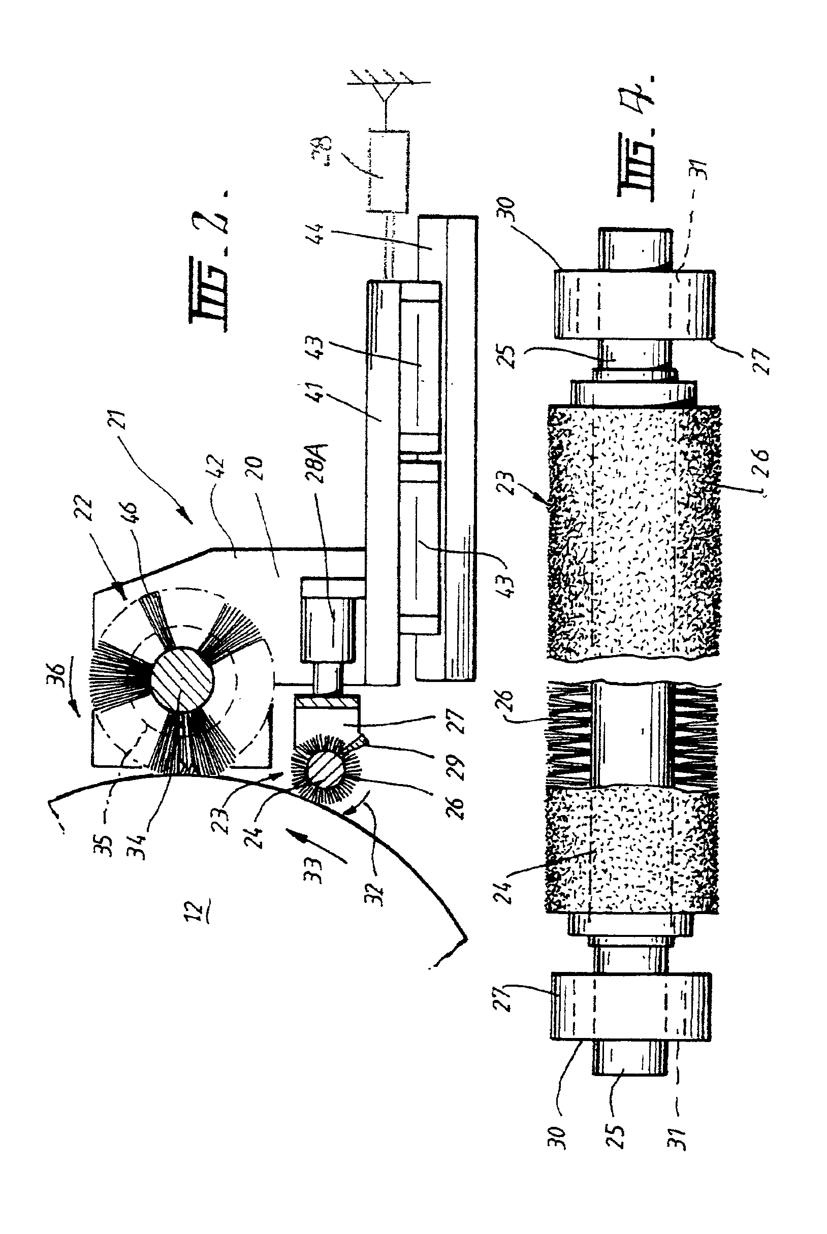
The patent describes an apparatus for casting metal strip, which includes a casting roll, a metal delivery system, and a roll brushing apparatus. The brushing apparatus has a main brush and a sweeper brush that work together to clean the roll surface during casting. The sweeper brush is mounted on a separate frame or can move independently of the main brush. The sweeper brush is actuated by a fluid cylinder device and is moved in and out to engage the casting roll at the start and end of the casting run. The apparatus also includes an elongate scraper to remove any swept material from the sweeper brush. The technical effect of this invention is to provide an efficient and effective way to clean the roll surface during casting without causing damage or wear to the surface.

Problems solved by technology

It has been found that during the start and finish of a casting operation, the casting roll picks up major accretions of contaminants and these can damage the brushing device which must be capable of performing fine cleaning of the casting surface during normal casting.
The contaminants can also damage the casting roll surface if they accumulate between the casting rolls and the metal delivery support plate.

Method used


Image

  • Strip casting apparatus
  • Strip casting apparatus
  • Strip casting apparatus

Examples


Embodiment Construction

[0019]The embodiments are described with reference to a twin roll caster, but they are not limited to use with twin roll casters. The illustrated twin roll caster comprises a main machine frame 11 which supports a pair of parallel casting rolls 12 of generally textured outer peripheral longitudinal surfaces. Molten metal is supplied during a casting operation from a ladle 13 through a refractory ladle outlet shroud 14 to a tundish 15 and thence through a metal delivery nozzle 16 into the nip 17 between the casting rolls 12. Hot metal thus delivered to the nip 17 forms a pool 10 above the nip and this pool is confined at the ends of the rolls by a pair of side closure or side dam plates 18 which are held against stepped ends of the rolls by actuation of a pair of hydraulic cylinder units (not shown). The upper surface of the pool 10 (generally referred to as the “meniscus” level) may rise above the lower end of the delivery nozzle so that the lower end of the delivery nozzle is immer...


PUM

PropertyMeasurementUnit
cylindrical shapeaaaaaaaaaa
movementaaaaaaaaaa
widthaaaaaaaaaa

Abstract

An apparatus for casting metal strip in which molten metal is applied to a casting roll the surface of which is cleaned by a cleaning brush device comprising a main brush extending across the roll surface by sweeper brush actuator 28A and a sweeper brush extending across the roll and capable of tangentially engaging the peripheral longitudinal roll surface in advance of the main brushing device. Both brushes are mounted on mounting frames moveable to bring the main and sweeper brushes into contact with the casting roll. The sweeper brush is independently moveable on the frame by operation of an sweeper brush actuator to move the sweeper brush into engagement with the surface of the casting roll near the start and end of the casting run and the main brush actuator to move the main brush into engagement with the peripheral longitudinal surface of the casting roll during normal casting operation.

Description

CROSS-REFERENCE TO RELATED APPLICATIONS[0001]This is a continuation-in-part of U.S. utility patent application Ser. No. 09 / 324,000, filed Jun. 2, 1999 now abandoned, which claims the benefit of Australian provisional patent application No. PP 4143, filed Jun. 17, 1998.BACKGROUND OF THE INVENTION[0002]This invention relates to a metal strip casting apparatus in which molten metal is brought into contact with a casting roll surface so as to solidify on that surface. More specifically, it is concerned with cleaning of the casting rolls in such casters.[0003]The casting apparatus may be either a single roll caster or a twin roll caster. In a twin roll caster hot metal is introduced between a pair of contra-rotated horizontal casting rolls which are cooled so that metal shells solidify on the moving roll surfaces and are brought together at the nip between them to produce a solidified strip product at the outlet from the roll nip. The term “nip” is used herein to refer to the general reg...

Claims


Application Information

Patent Timeline
Patent Type & Authority Patents(United States)
IPC IPC(8): B22D11/06
CPCB22D11/0674
Inventor KATO, HEIJIFISH, JOHN ANDREWRUSSELL, WAYNE
Owner NUCOR CORP
Learn More