Elevator load bearing assembly having a detectable element that is indicative of local strain

a technology of load bearings and assemblies, applied in the direction of elevators, instruments, force/torque/work measurement apparatus, etc., can solve the problems of limited inspection methods, no indication of exterior portions of ropes, and no indication of local strain

Inactive Publication Date: 2005-05-03
OTIS ELEVATOR CO
View PDF17 Cites 25 Cited by
  • Summary
  • Abstract
  • Description
  • Claims
  • Application Information

AI Technical Summary

Problems solved by technology

This inspection method is limited, however, to the exterior portions of the rope and does not provide any indication of the condition of interior strands of the rope.
Additionally, this inspection method is somewhat difficult and time consuming and does not always permit complete inspection of the entire length of the load bearing arrangement.
There are similar limitations on using visual inspection techniques on newer ropes.
For example, the polymer coated reinforced belts

Method used


Image

  • Elevator load bearing assembly having a detectable element that is indicative of local strain
  • Elevator load bearing assembly having a detectable element that is indicative of local strain
  • Elevator load bearing assembly having a detectable element that is indicative of local strain

Examples


Embodiment Construction

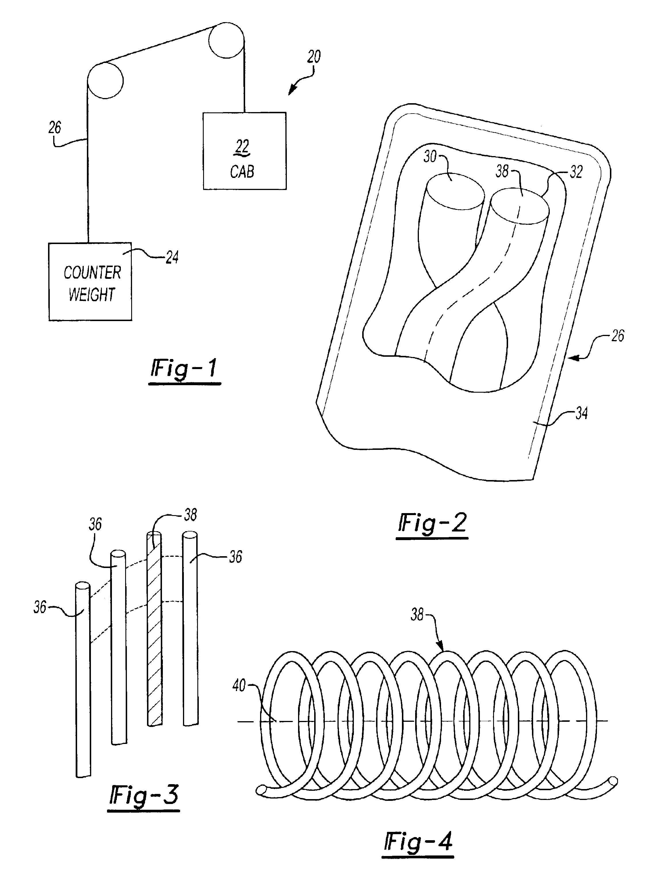
[0018]FIG. 1 schematically shows an exemplary elevator system 20 that includes a cab 22 and a counterweight 24. A load bearing member assembly 26 couples the cab 22 and counterweight 24 together so that the cab 22 can be moved between landings in a building, for example, in a conventional fashion.

[0019]The load bearing member assembly 26 may take a variety of forms. One example is a flat belt containing polymer reinforced strands. Other examples include flat, coated steel belts; synthetic ropes; and multi-element ropes. This invention is not limited to “belts” in the strictest sense. A flat belt is used as one example of a load bearing member designed according to this invention. Therefore, any reference to a “belt” within this description is not intended to be limiting in any sense.

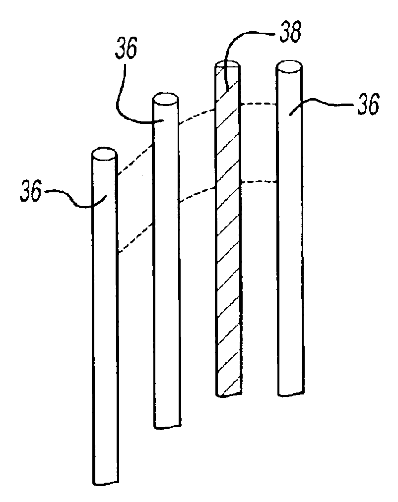
[0020]The example load bearing member assembly 26 shown in FIG. 2 includes a plurality of strands 30 and 32 that are wound together in a known manner to form at least one cord. A first material preferabl...


PUM


Abstract

A load bearing member, such as a polymer cord reinforced belt, includes at least one element of a different material having a characteristic that distinguishes it from the polymer fibers that make up the strands of the cord. The element of second material has a configuration that is repeated along the length of the load bearing member. The configuration of the second material element provides a readily detectible indication of localized strain on the load bearing member. As the load bearing member is strained over time, the configuration of the second material element is also altered. Analyzing the configuration of the second material element along the length of the load bearing member provides information regarding the condition of the belt.

Description

[0001]This application is a Continuation of U.S. Patent application Ser. No. 09 / 970,451, which was filed on Oct. 3, 2001, now abandoned.BACKGROUND OF THE INVENTION[0002]This invention generally relates to load bearing assemblies for elevator systems. More particularly, this invention relates to an arrangement for readily detecting localized strain in an elevator load bearing assembly.[0003]Elevator systems typically include a cab and counterweight that are coupled together using an elongated load bearing member. Typical load bearing members include steel ropes and, more recently, synthetic ropes and multi-element ropes such as polymer coated reinforced belts. The increasing use of elevators in high-rise buildings has given rise to the need for an increasing use of the polymer coated reinforced belts because of their weight-to-strength ratios compared to steel roping arrangements.[0004]Inspecting a load bearing member in an elevator system has been accomplished in several ways. With ...

Claims


Application Information

Patent Timeline
IPC IPC(8): B66B7/12D07B1/14D07B1/00B66B5/02B66B7/06D02G3/04D02G3/12D02G3/28
CPCB66B7/123B66B7/1238B66B7/1215D07B1/145D07B2501/2007D07B2301/555
Inventor STUCKY, PAUL A.BALDWIN, NEIL R.LAVRENTYEV, ANTON I.VERONESI, WILLIAM A.
Owner OTIS ELEVATOR CO
Why Eureka
Try Eureka