
Driving method of piezoelectric elements, ink-jet head, and ink-jet printer

a technology of piezoelectric elements and driving methods, which is applied in the direction of printing, other printing apparatus, etc., can solve the problems of increasing the head temperature, ejection failure, and fluctuation of ejection characteristics, so as to reduce the power dissipation

Inactive Publication Date: 2005-05-03
SHARP KK
View PDF11 Cites 9 Cited by
  • Summary
  • Abstract
  • Description
  • Claims
  • Application Information

AI Technical Summary

Benefits of technology

[0006]The present invention was made to solve the foregoing problems and accordingly it is an object of the present invention to provide a driving method of piezoelectric elements, by which a driving voltage, generated heat, and power dissipation can be reduced.
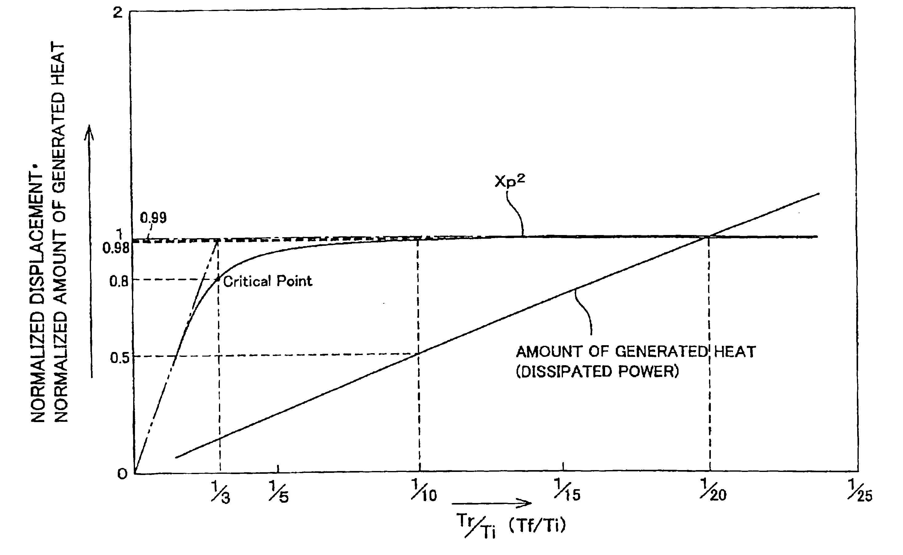
[0010]In this way, the present driving method can eliminate a loss due to a resistor component of a charge / discharge system, such as wiring or switching elements, caused by a large current that is flown when Tr and / or Tf are too small. As a result, heat generation as well as power dissipation can be suppressed.

Problems solved by technology

However, a rise time or a fall time that is too short causes the generated heat to accumulate and this increases the head temperature, with the result that ejection characteristics may fluctuate or ejection failure may occur.
Another problem is that it increases dissipated power.

Method used


Image

  • Driving method of piezoelectric elements, ink-jet head, and ink-jet printer
  • Driving method of piezoelectric elements, ink-jet head, and ink-jet printer
  • Driving method of piezoelectric elements, ink-jet head, and ink-jet printer

Examples


Embodiment Construction

[0023]One embodiment of the present invention is described below.

[0024]A printer according to the present embodiment (“present printer” hereinafter) has a function of receiving image data from an external information processing device such as a computer or a digital camera, and processing the image data, so as to print its image on a printing sheet such as paper or plastic for output.

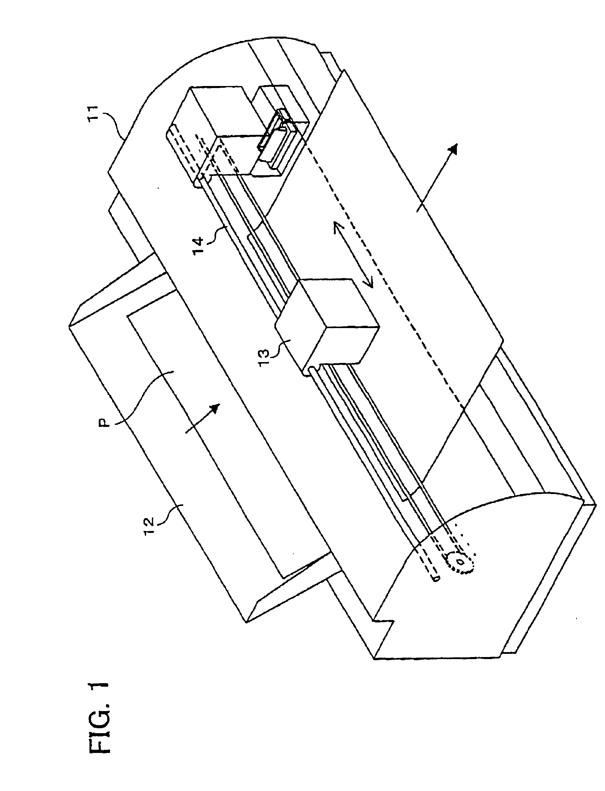
[0025]FIG. 1 is a perspective view showing a configuration of the present printer. As shown in FIG. 1, the present printer includes a sheet guide 12, an ink-jet head 13, a holding shaft 14, and transport rollers (not shown), which are all provided within a casing 11 along with other components.

[0026]The present printer further includes a control section (not shown), which receives image data that was transmitted from an information processing device such as a computer (not shown) and controls the foregoing printer components to carry out a print job.

[0027]The sheet guide 12 serves as a feeder tray and / o...


PUM


Abstract

A rise time and / or a fall time of a driving voltage are set to be not less than {fraction (1 / 20)} of a period of natural oscillation of an ink-jet head. This suppresses a driving voltage, an amount of generated heat, and dissipated power, which increase when there is a loss due to a resistor component of a charge / discharge system, such as wiring or switching elements, caused by a large current that is flown when the driving voltage rises or falls sharply. The rise time and / or fall time may be made not more than ⅓ of the period of natural oscillation. In this way, 80% or higher efficiency can be ensured for the oscillation energy of piezoelectric elements, which increases as the rise or fall of the driving voltage becomes sharper. Further, the rise time and / or fall time may be set in the vicinity of {fraction (1 / 20)} of the period of natural oscillation. In this way, the ejection energy of the piezoelectric elements can be saturated almost completely. As a result, less driving voltage, less heat, and less power are required to drive piezoelectric elements, which are used in ink-jet recording apparatuses and other types of apparatuses.

Description

FIELD OF THE INVENTION[0001]The present invention relates to a driving method of piezoelectric elements for driving piezoelectric elements of various devices, such as an ink-jet head of ink-jet printers, ultrasonic washing machines, ultrasound humidifiers, and ultrasonic motors, by applying a rectangular or trapezoidal wave thereto. The invention also relates to an ink-jet head that employs such a driving method, and an ink-jet printer that is provided with such an ink-jet head.BACKGROUND OF THE INVENTION[0002]An ink-jet head of ink-jet printers is provided with a less than half the natural period Tc of the ink pressure chambers. This intends to improve ejection efficiency in low-voltage driving.[0003]Further, Japanese Publication for Unexamined Patent Application No. 6-305134 (published on Nov. 1, 1994) discloses a technique that relates to an ink-jet head and a driving method of the inkjet head. This technique teaches that T1, T2≧Tc, and T1, T2≧Ta, where Ta is the period of natura...

Claims


Application Information

Patent Timeline
IPC IPC(8): B41J2/045
CPCB41J2/04541B41J2/04588B41J2/04581B41J2/04573
Inventor KOJOH, YOSHIAKIISHII, HIROSHI
Owner SHARP KK
Learn More