Pulsed vacuum and/or flow method and apparatus for tissue removal

a vacuum and flow technology, applied in the field of surgical instruments, can solve the problems of difficult vitreous surgery, pneumatically driven devices that cannot operate effectively at very low speeds, and surgical instruments suitable for vitreous surgery may not be suitable for retinal surgery, etc., and achieve the effect of low cut ra

Inactive Publication Date: 2005-05-03
JOHNSON & JOHNSON SURGICAL VISION INC
View PDF15 Cites 310 Cited by
  • Summary
  • Abstract
  • Description
  • Claims
  • Application Information

AI Technical Summary

Benefits of technology

[0017]Still more particularly, in accordance with the present invention, the speed of the blade movement in moving between the first and second positions may be regulated to control the amounts of tissue severed during the blade movement. In combination therewith, the vacuum may be regulated to obtain a predictable bite, or severed amount of tissue, with a predictable amo

Problems solved by technology

The presence of these fibers make vitreous surgery quite difficult, due to the possibility of retinal injury occurring if one of these fibers inadvertently severed.
Thus, a surgical instrument suitable for use in vitreous surgery may not be suitable for use in retinal surgery.
It is well known that such pneumatically driven devices do not operate effectively at very low speeds and are designed for operatio

Method used


Image

  • Pulsed vacuum and/or flow method and apparatus for tissue removal
  • Pulsed vacuum and/or flow method and apparatus for tissue removal
  • Pulsed vacuum and/or flow method and apparatus for tissue removal

Examples


Embodiment Construction

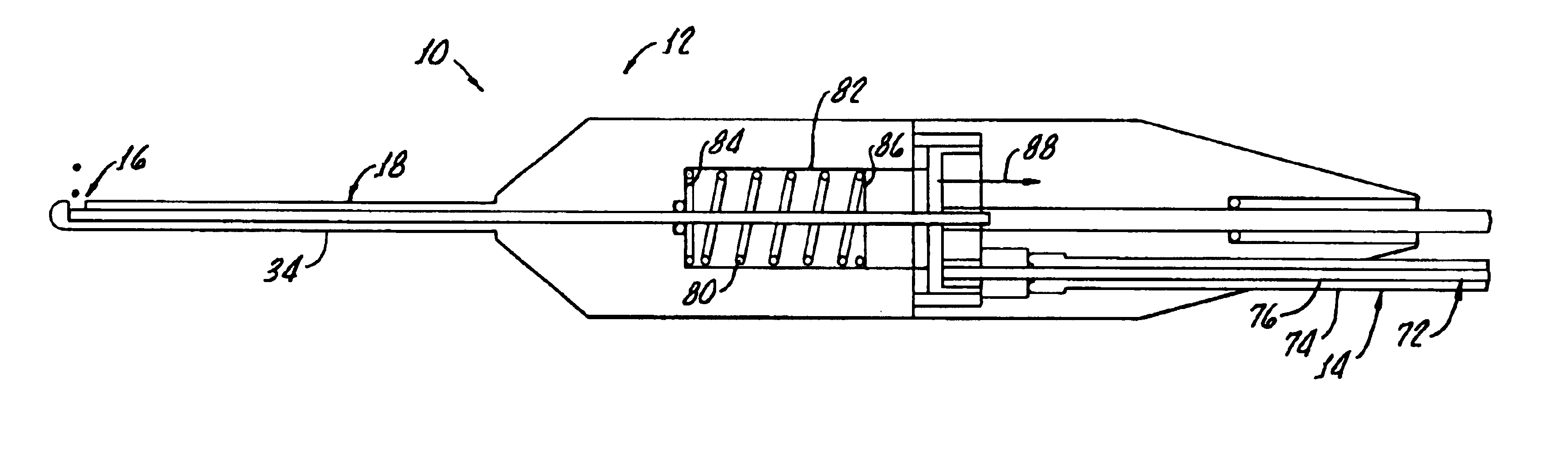
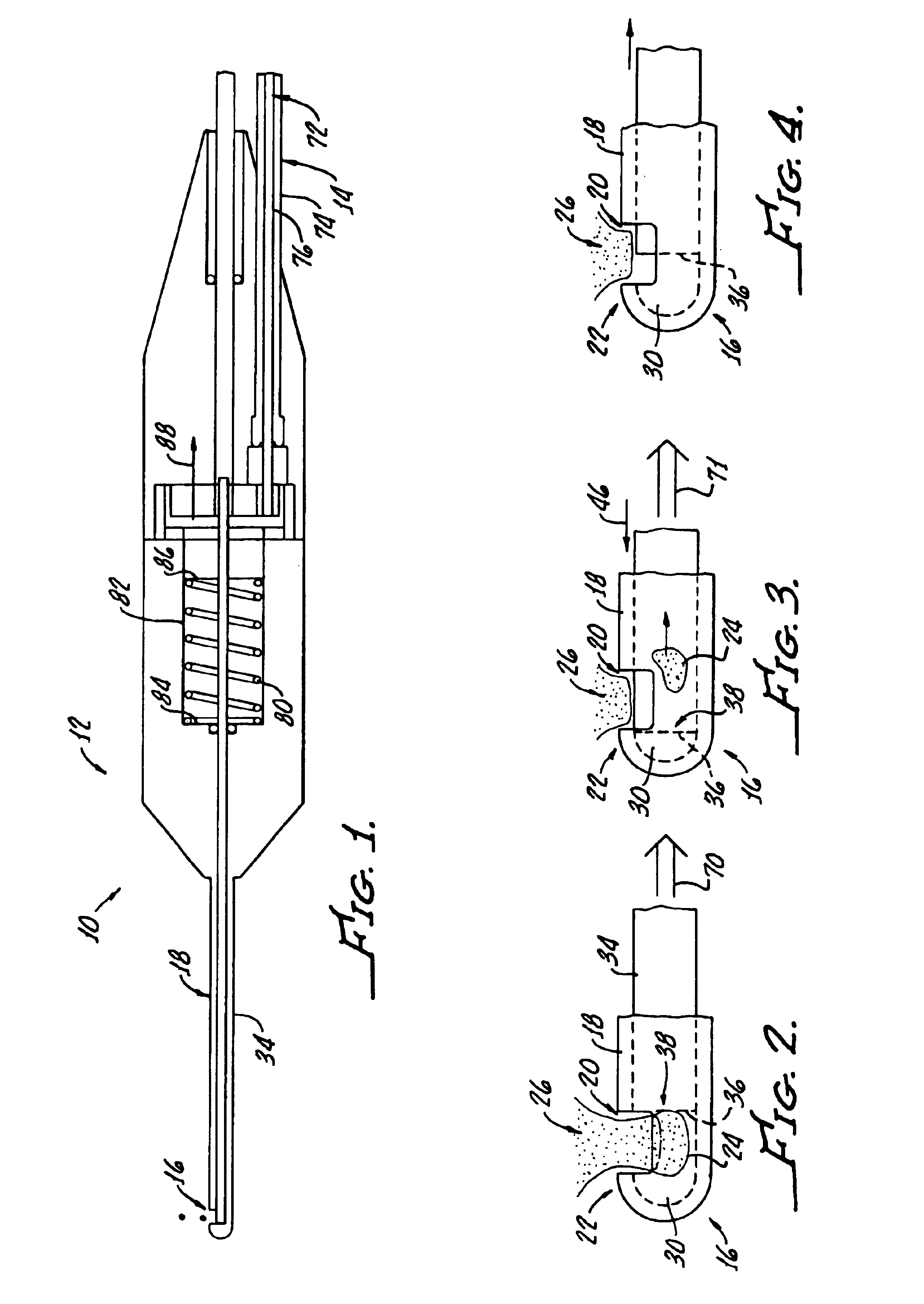
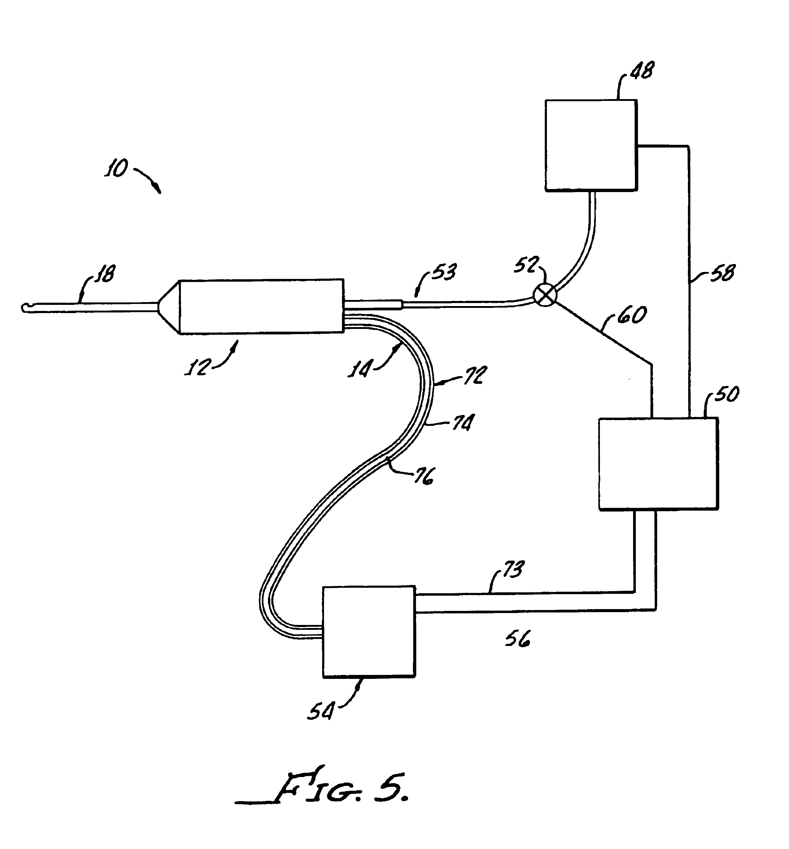
[0024]Turning now to FIG. 1, there is shown surgical cutting apparatus 10, in accordance with the present invention, which generally includes a probe 12 as means for cutting tissue of a body (not shown in FIG. 1), and a driver 14 for causing the cutting action of the probe 12 as hereinafter described. It should be appreciated that the driver 14 is shown as a mechanical device for illustration purposes, alternate drivers, not shown, such as pneumatic drivers may be utilized.

[0025]More particularly, the probe 12 includes a needle 16 which is shown in detail in FIGS. 2-4. The needle 16 includes an outer sleeve 18 having an opening, or port 20, proximate a distal end 22 of the outer sleeve 18 as means for enabling entry of a portion 24 of tissue to be cut from the body 26 of tissue. The body 26 of tissue may be a vitreous humor of an eye, a retina of the eye, or any other body of tissue located in a confined area of a patient, such as to require the use of a narrow probe to access same....


PUM


Abstract

A method of controlling a surgical cutting device, the device including a hollow needle with a port for tissue entry and a moveable cutting blade for severing tissue entering the needle through the port, the blade being movable between a first portion enabling tissue entry through the port and a second portion closing the port, the tissue entering the needle being severed as the blade moves between the first and second portions, the method includes the steps: a) providing vacuum to the hollow needle to cause tissue entry into the needle through the port; b) moving the blade from the first portion to the second position to sever the tissue entering the needle; c) evacuating severed tissue from the needle by vacuum; d) reducing vacuum to the needle before moving the blade from the second position to the first position; and repeating steps (a) through (d).

Description

[0001]The present invention generally relates to surgical instruments and more particularly relates to a tissue cutting surgical device suitable for use in vitreous and retinal surgery.[0002]An eye surgery procedure performed behind the lens is called vitreous surgery in as much as the posterior chamber of the eye is filled with a transparent jelly called the vitreous humor (“vitreous”).[0003]Understandably, vitreous surgery, as with any ophthalmic surgical procedure, requires great precision. The vitreous is filled with numerous fiber like materials, some of which are attached to the delicate retina. The presence of these fibers make vitreous surgery quite difficult, due to the possibility of retinal injury occurring if one of these fibers inadvertently severed.[0004]Moreover, retinal surgery, which involves actual cutting of the retina of the eye, must be performed with even greater precision, as the retina is the immediate instrument of vision and is directly connected with the b...

Claims


Application Information

Patent Timeline
IPC IPC(8): A61F9/007
CPCA61F9/00763
Inventor KADZIAUSKAS, KENNETH E.ROCKLEY, PAUL W.COLE, MARK S.
Owner JOHNSON & JOHNSON SURGICAL VISION INC
Why Eureka
Try Eureka