Variable stiffness heating catheter

a heating catheter and variable stiffness technology, applied in the field of interventional medical devices, to achieve the effect of variable stiffness of the heating catheter

Inactive Publication Date: 2005-05-03
MICRUS CORP
View PDF270 Cites 125 Cited by
  • Summary
  • Abstract
  • Description
  • Claims
  • Application Information

AI Technical Summary

Benefits of technology

[0008]Briefly, and in general terms, the present invention provides for a variable stiffness heating catheter shaft formed from a heating catheter and a reinforcing tube over at least a portion of the heating catheter, with apertures being formed around the surface of the reinforcing tube and extending in a direction between the proximal and distal ends of the heating catheter, to provide variable stiffness to the heating catheter shaft. Typically, such a heating catheter shaft can be formed from one or more electrically conductive members or the like which alone have physical characteristics that are undesirable for guidewires or pusher devices. By use of the invention, a variable stiffness heating catheter shaft can be made which is more pushable at the proximal end and more trackable at the distal end, with the capability to provide a wide range of predictable variations in stiffness and other structural parameters over the length of the shaft. A variable stiffness heating catheter constructed according to the invention can be used in conjunction with a guide catheter or as a flow directed, stand alone catheter.
[0009]By using the construction according to the invention, coating or heat shrinking a heat shrinkable material on the outside diameter of the heating catheter shaft will improve tracking of the device, and a taper can also be ground onto the heating catheter shaft to yield a shaft with a stiffer, more manageable, proximal end and a softer, more maneuverable, distal tip. The variable stiffness heating catheter advantageously can also thus be constructed from a minimum number of components, with the apertures in the reinforcing tube eliminating the need for a braid or transitional sections from the stiffer proximal zone to the softer distal zone.
[0011]In one presently preferred embodiment, the apertures can be formed as longitudinal, axial slits, slots, channels, or grooves in the surface of the reinforcing tube, and in an alternate preferred embodiment, the apertures can be formed as helical or radial slits, slots, channels, or grooves in the surface of the reinforcing tube, providing variable stiffness to the heating catheter. The outer surface of the reinforcing tube can also be formed to be tapered at the point where the apertures are formed in the reinforcing tube, particularly at a distal portion of the heating catheter, to provide a heating catheter that is torqueable and pushable at the proximal end, yet soft and flexible at the distal end. Alternatively, the apertures can be formed transversely in the surface of the reinforcing tube in an area where such a configuration will produce desired results.
[0012]The one or more coaxial layers can be formed of heat shrink polymeric material, such as polyethylene, polytetrafluoroethylene (PTFE) polyethylene terephthalate (PET), polyetherethylketone (PEEK), polyphenylenesulfide (PPS), or any of a variety of other polymers which can be fabricated into a structure and necked or shrunk over a shaft, or can be formed of metal. While the invention can effectively use tubes which are placed over the exterior of the heating catheter shaft and then heat shrunk or bonded by adhesive to the heating catheter shaft, it is also contemplated that the heating catheter shaft can be reinforced by other longitudinally extending additional structures with varying cross sections for certain specific applications.
[0013]The heat shrink tubing is placed on the heating catheter shaft, and then heat can be applied to the heat shrink tubing, resulting in shrinkage of the heat shrink tubing to encapsulate the heating catheter shaft. The structure formed by the apertures in the surface of the reinforcing tube, in combination with the distal taper of the reinforcing tube and outer coaxial sheath, allows the proximal part of the composite shaft to be relatively stiff, and the distal tip to be flexible and soft. A variety of other techniques can be used within the scope of the invention to accomplish the variable stiffness of the heating catheter.

Problems solved by technology

Typically, such a heating catheter shaft can be formed from one or more electrically conductive members or the like which alone have physical characteristics that are undesirable for guidewires or pusher devices.

Method used


Image

  • Variable stiffness heating catheter
  • Variable stiffness heating catheter
  • Variable stiffness heating catheter

Examples


Embodiment Construction

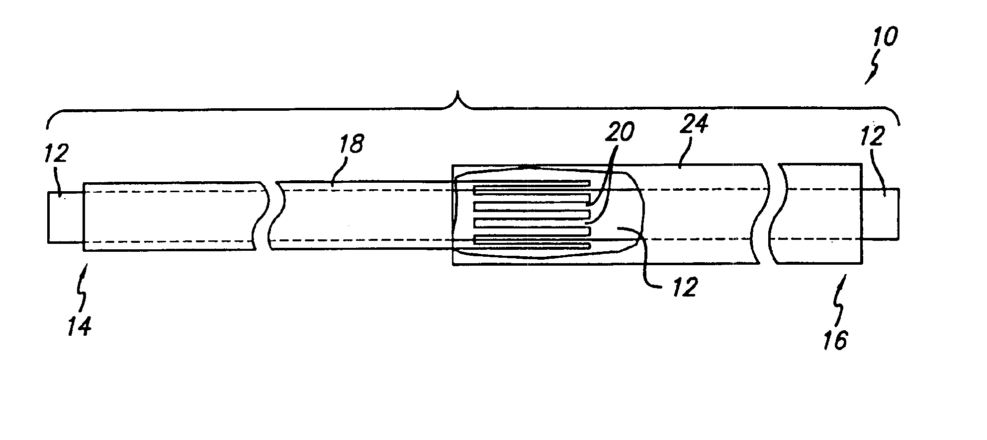
[0033]Modern interventional medical procedures have relied on ever smaller and more flexible devices to reach areas requiring treatment which were previously inaccessible to conventional devices, such as by the placement of vasoocclusive devices in tiny areas of damaged vasculature such as aneurysms or ruptures in arteries in the brain. Some devices to treat such areas use optical fibers to carry light energy to remote locations at the distal end of the heating catheter, but certain limitations have been found in currently available optical fibers for those purposes.

[0034]For example, conventional heating catheter technology has not been easily adaptable to catheter based imaging, treatments such as “thrombolyzing” blood or cutting tissue, or to the delivery of therapeutic agents, such as timed release agents, or embolics, since optical fibers, when used as a stand alone structural device, are not very torqueable, pushable or resilient. Small diameter optical fibers of the type most...


PUM


Abstract

The variable stiffness heating catheter includes a heating catheter shaft including at least one electrically conductive member, a reinforcing tube with apertures formed around the surface of the reinforcing tube, and at least one coaxial outer layer of a polymer, metal, or both for providing desired variations in stiffness along at least a portion of the length of the shaft. The apertures can be formed as axial or helical slits in the surface of the reinforcing tube, and the reinforcing tube can also be formed to be tapered at the point where the apertures are formed in the reinforcing tube to provide a heating catheter that is torqueable and pushable at the proximal end, yet soft and flexible at the distal end.

Description

RELATED APPLICATIONS[0001]This is a continuation-in-part of Ser. No. 09 / 275,485 filed Mar. 24, 1999, now U.S. Pat. No. 6,352,531.BACKGROUND OF THE INVENTION[0002]1. Field of the Invention[0003]This invention relates generally to interventional medical devices, and more particularly concerns a heating catheter having variable stiffness for enhanced performance of the catheter shaft when used with or without a guide catheter, as a part of a therapeutic system or for delivery of medical devices.[0004]2. Description of Related Art[0005]Conventional minimally invasive catheter based therapies typically require guide wires that are one to two meters long extending through a longitudinal lumen in the catheter, and that are torqueable and pushable at the proximal end, yet soft and flexible at the distal end. Many such guidewires are made of stainless steel or the like, and are ground to tapers which provide the desired bending properties along the guidewire. Recently, numerous minimally inv...

Claims


Application Information

Patent Timeline
Patent Type & Authority Patents(United States)
IPC IPC(8): A61M25/00A61B18/20A61B18/24
CPCA61M25/00A61M25/0053A61B18/24A61M2025/0064A61M25/0051
Inventor O'CONNOR, MICHAEL J.FERRERA, DAVID A.CONNORS, MATTHEW
Owner MICRUS CORP
Why Eureka
Try Eureka